Week 5: Electronics design
Background
For this project, we were asked to use an EDA tool to design a development board to interact and communicate with an embedded microcontroller.
Materials
Idea
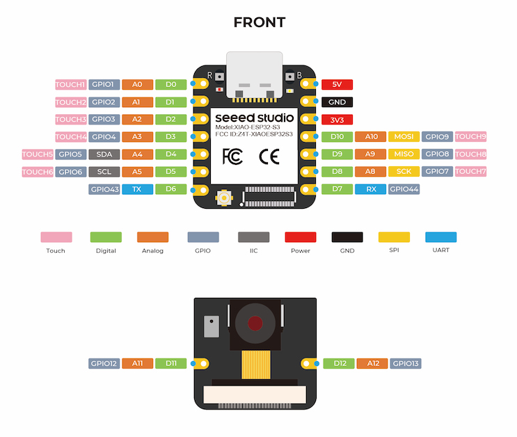
For this week, I wanted to start piecing together a prototyping board so I could start controlling stepper motors with a camera module as input on an ESP32S3 (see datasheet here ).
The ESP32-S3 consists of high-performance dual-core microprocessor, a low power coprocessor, a Wi-Fi baseband, a Bluetooth LE baseband, RF module, and numerous peripherals.
Goal
First up, you need to determine what you want your circuit board to do. In my case, I wanted to create a development board with an embedded microcontroller that would be able to both sense and actuate stepper motors.
Components
Next, what components do you need to include in your circuit? List them out and their respective connections (power, ground, data, etc.)
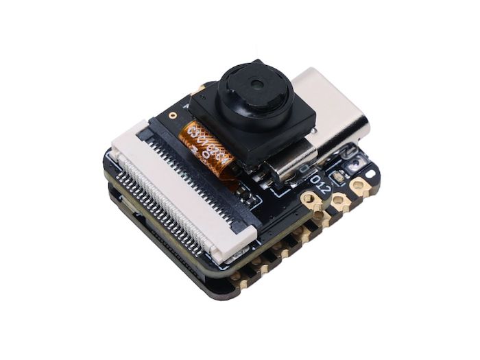
In my case, I needed a camera to connect to the ESP32S3's B2B connector, so I picked the OV2640 (pictured below). Beyond that I wanted to make sure I included plenty of data controls and extra power hookups for motor drivers, joystick controls, and other peripherals I plan on testing with in later weeks.
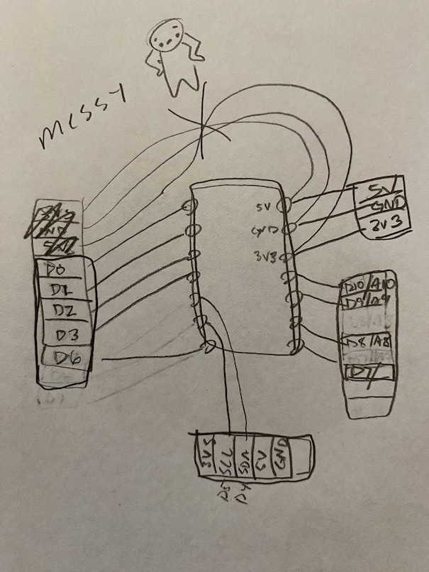
Sketching
This is definitely optional, but it helped me understand how to connect my board when I could draw lines between components first (i.e. sketch your whole board out). Starting out on Eagle is a pain in the ass, so I highly recommend making sure you know exactly what you're trying to create before starting to use any EDA software.
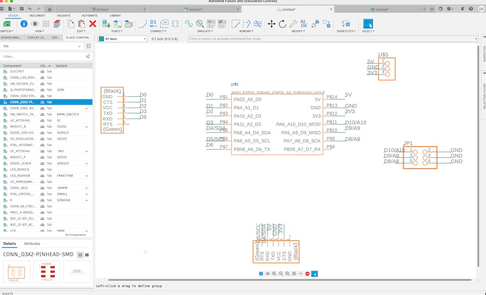
EDA
To outline your PCB design/schematic, open up an EDA software of your choice (I used Eagle in Fusion360) and start with the schematic view. There, place all the components you plan on working with in your schematic view, THEN worry about labeling each components with its respective connection.
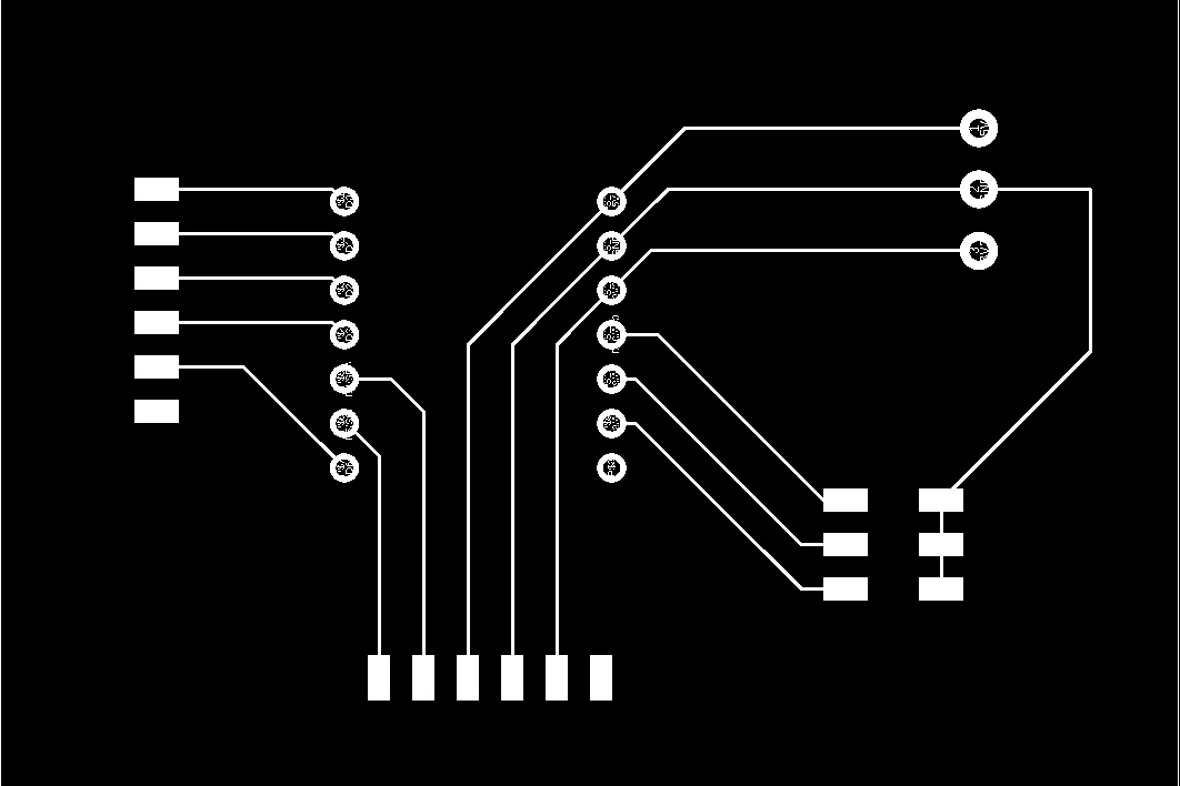
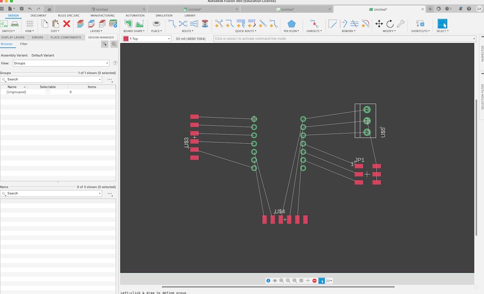
Once that was done, I switched over to PCB view, modified the size of my overall board and manually routed connections between my various components. The auto-route function we were warned about definitely sucks, but it was interesting to see where it would fail to realize its mistakes (cutting corners too close, overlapping lines, etc.)
I then went to the command line to export my layers to a PNG file that the CNC machine will be able to use in coming weeks, and used the following command to export my design to a monochrome PNG file with a DPI of 400:
export image schematic.png monochrome 400
The final product
To be honest, this isn't my best work. I need to clean this PNG up in Photoshop if I realistically want to print it. It includes the labels from my schematic because I didn't have access to a simplified command called 'run singleImages' that the teaching team had created for this, and had to rely on Fusion 360 help articles... which are incredibly low quality and hard to understand.
Moving into next week, I plan on clarifying if this is the right output (pictured below) and how I can create my own scripts in Eagle for exporting ease.
If you'd like to recreate this project, you can download my PNG files here.