Week 6: Electronics production
Background
For this project, I made and tested the development board that I designed last week.
Materials
Idea
This week was all about learning how to mill your own PCB board. The schematic I created last week is a development board that enables me to more easily connect jumper wires, sensors, and other peripherals to the microcontroller.
As an interesting side note, the SRM-20 is a pretty powerful tool! It's the desktop milling machine we used for this week, but it can also be used to precision mill other materials like modeling wax, foam, acrylic, and much more.
Fixing my schematic
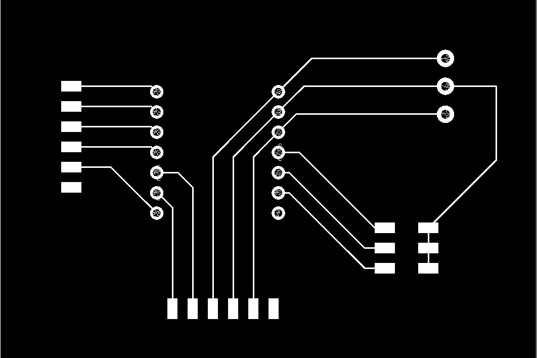
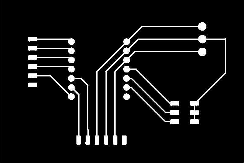
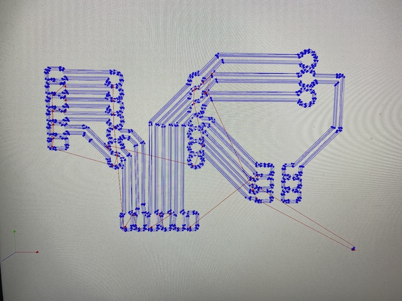
The PNG that I ended up with last week had a few issues I needed to fix before I could start the printing process (bottom left image). After wanting to pull my hair out with Fusion 360, I resorted to Adobe Illustrator (like I always do) to get rid of the text, make all the pads totally filled in, and increase the route width to .1". Then, I exported the new schematic image (bottom middle image) w/ its respective outline (bottom right image) as PNG's from Illustrator.

Setup
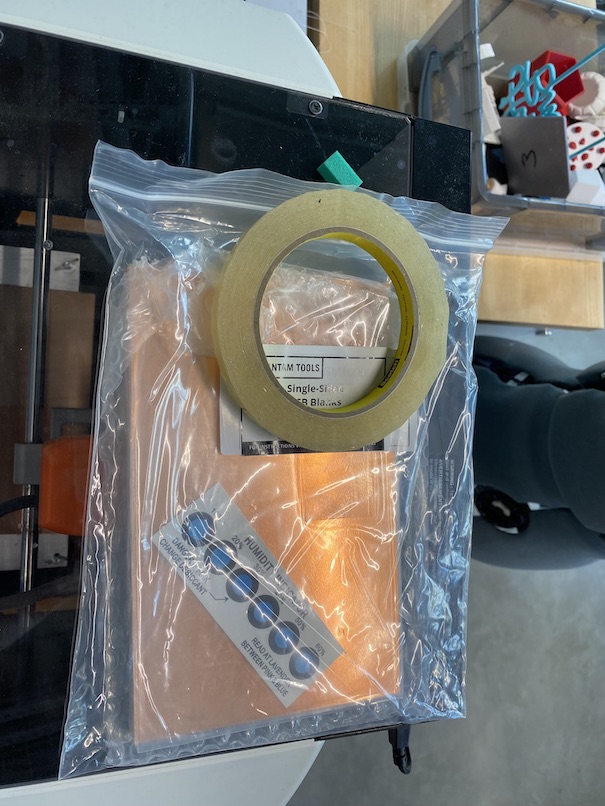
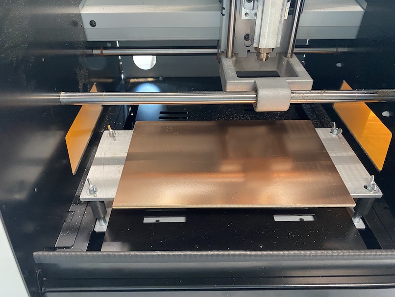
To ensure you don't hurt the bed on the milling machine, you'll need to secure a sacrificial layer under the PCB blank you intend on milling. I used an old PCB board for this. Then, secure the PCB blank you intend on milling on top of that with double-sided tape-- nothing fancy here. Now, your setup should look like the photo on the right.
Next, turn on the machine and make sure it's plugged in to your computer via the webUSB connection. From here, I followed the TA's instructions that were posted here. Contrary to the way I typically document these weeks, I'm going to keep this in bullet point formatting for ease of parsing.
- Go to [mods website](https://modsproject.org/)
- Right click to open the menu
- Select 'programs'
- Select 'open program'
- Select 'SRM-20 mill' > 'PCB'
Milling the traces
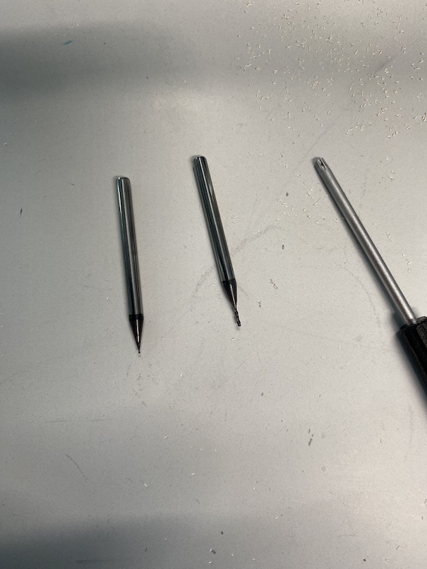
Now that you've selected the milling program you intend on using, you'll need to select the file you intend on using for the designs on top of your board. Traces are always milled first and include pads, routes, and other components you included in your schematic. These will be milled to a depth that engraves through the PCB conductive layer, but won't cut through the whole board like the outline will. In this board, I used a 1/64" endmill(pictured on left) for my traces and a 1/32" endmill (pictured on right) for my outline. If at any point in the milling process you see a blinking light on the back right of the top of the machine, it means it performed an emergency reset. You'll need to turn the machine off and back on to start all over again.
- Select your PNG
- Hit 'mill traces'
- Click 'Calculate', then wait for a moment as the toolpaths generate - mods uses RML, which serves the same purpose as Gcode to a 3D printer
- Hit 'Get Device'
- Select 'SRM-20'
- Insert the 1/64 in endmill
- Move to your desired x,y location at a safe z height (~50mm) - always start out higher than you think! You risk breaking a drill bit or scraping your board if it's too low.
- Use 'move to origin' to move the machine
- Set the z-axis to 10mm in the 'Home' section
- Loosen the endmill and lower it manually till it touches the copper plate then tighten it - this is an awkward process that requires you to bend your hand in weird shapes within the machine. If it feels wrong, you're probably doing the right thing here.
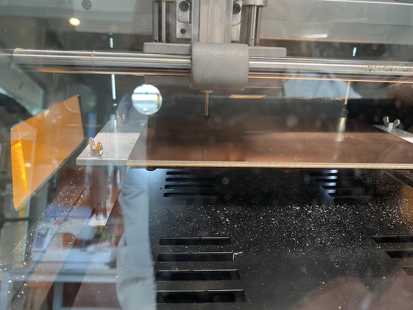
- Close the door and hit 'send file' - by sending the file, you're running the program. At first, the drill bit was hovering 10mm above my board for the entirety of the program (see photo below), so this step took a little bit of trial and error. If it is, stop the program and restart everything, this time using a lower z-height. I ended up using 10mm, but that might be subject to change.
- Vacuum - hold down your board with a pencil or something as you use a shop vac around your board. If you're not careful you'll scrape your board with the tip of the vacuum.
Milling the outline
Milling the outline is very similar to milling the traces. The only things that differ are your input image and endmill size.
- Select your PNG
- Hit 'mill outline'
- Click 'Calculate', then wait for a moment as the toolpaths generate
- Hit 'Get Device'
- Select 'SRM-20'
- Insert the 1/32 in endmill
- Move to your desired x,y location at a safe z height (~50mm)
- Use 'move to origin' to move the machine
- Set the z-axis to 10mm in the 'Home' section
- Loosen the endmill and lower it manually till it touches the copper plate then tighten it - this is an awkward process that requires you to bend your hand in weird shapes within the machine. If it feels wrong, you're probably doing the right thing here.
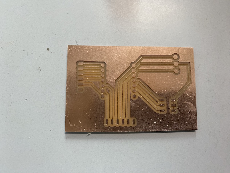
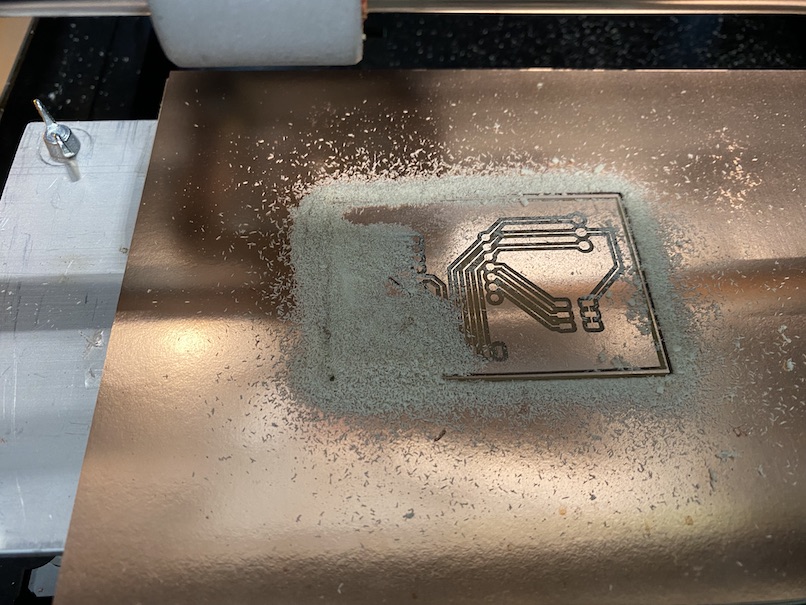
- Close the door and hit 'send file'- when your program is done, it should look like this:
- Vacuum - hold down your board with a pencil or something as you use a shop vac around your board. If you're not careful you'll scrape your board with the tip of the vacuum.
Soldering
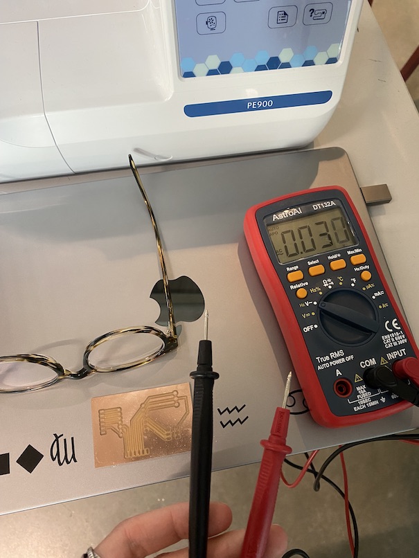
Before soldering, I was a little nervous my routes weren't thick enough to conduct electricity, so I used a multimeter to test various connections. Everything worked so I proceeded with soldering on some components.
- Gather all the components you want to add to your board
- Put on safety glasses and turn on local exhaust
- Turn on soldering iron
- Tape down loose components
- Solder joints
- Wipe down surfaces and wash hands
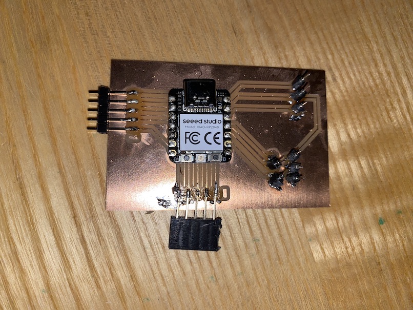
I ended up with the following board, which I'm NOT pleased with. Our lab didn't have the right header pins and connectors so I ended up melting plastic onto one pad, rendering that connection useless. At another point, I pulled away too abruptly and accidentally pulled up the conductive metal layer on my board. The final result is... uninspiring, to say the least. That said, if I was going to improve this in the future I'd get the right components first, then practice adding AND removing solder. I couldn't find braided wire in the lab, so that may have helped me remove unwanted connections. Overall, this was a neat week-- I learned a lot and definitely feel empowered.
If you'd like to recreate this project, you can download my SVG files here.