Nintengo Gamerboy
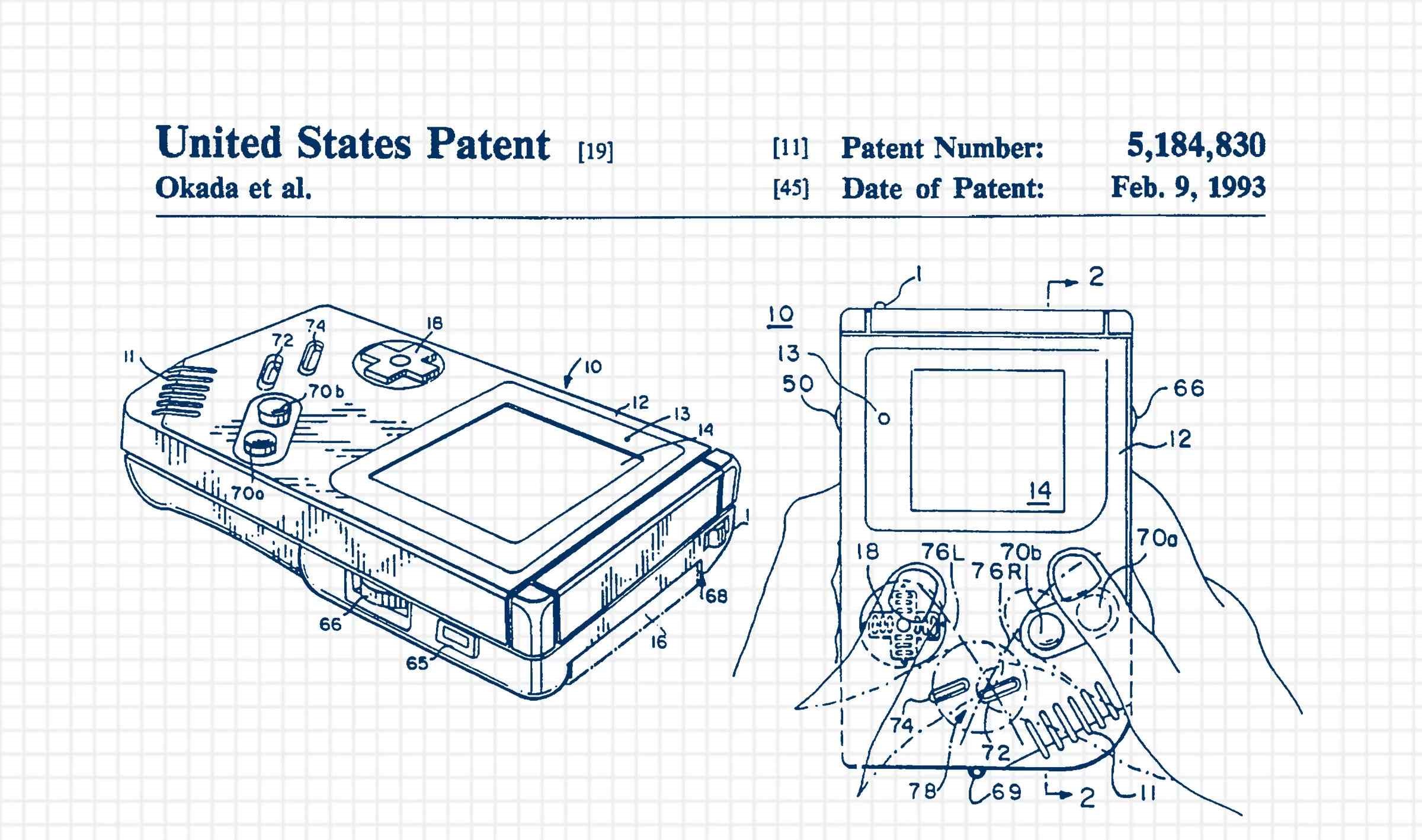
For my final project, I would like to try and make a reproduction of the original Nintendo Gameboy. I think that Nintendo products, besides being nostalgic, are a beautifully designed piece of hardware, and I would like to try and recreate one. I think that this project should involve nearly all of the skills that we are learning with the possible exception CAM.
I plan to build the case from an SLA printed clear chasis, and then laser cut and polish a piece of wood to act as the front. I would like to mold and cast the buttons and directional pad, but if that proves to go beyond the time constraints, I will 3D print them. I will then use a Pico W to act as the processor, a small LCD screen will replace the original black and white one, and a rechargeable LiPo battery will power the device.
In terms of programming the device, my initial goal will be to load an operating system that can emulate the original Gameboy. If I am able to do this, I would like to try and tackle writing the display driver myself, but I think this also may take far more time than I am anticipating.
Progress
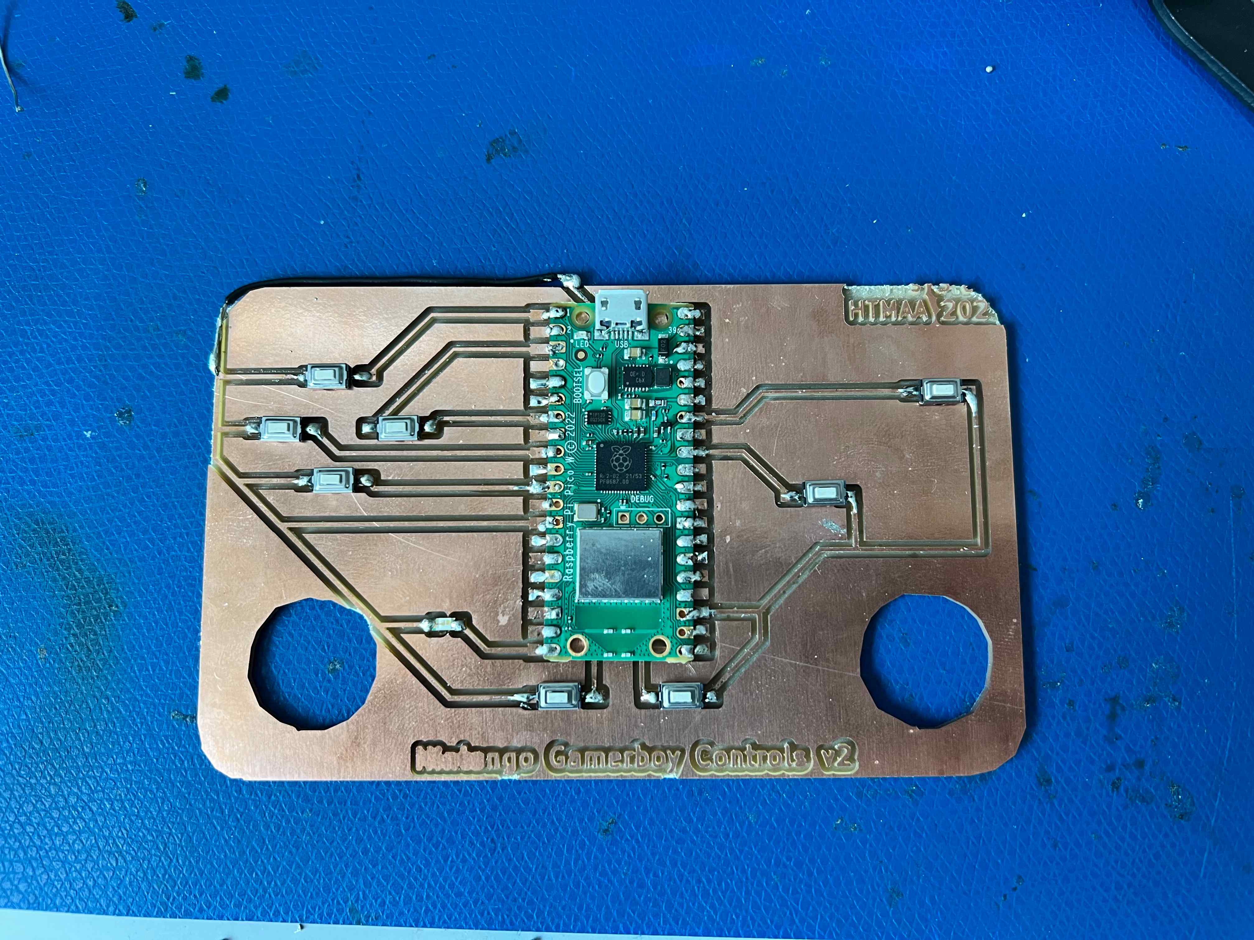
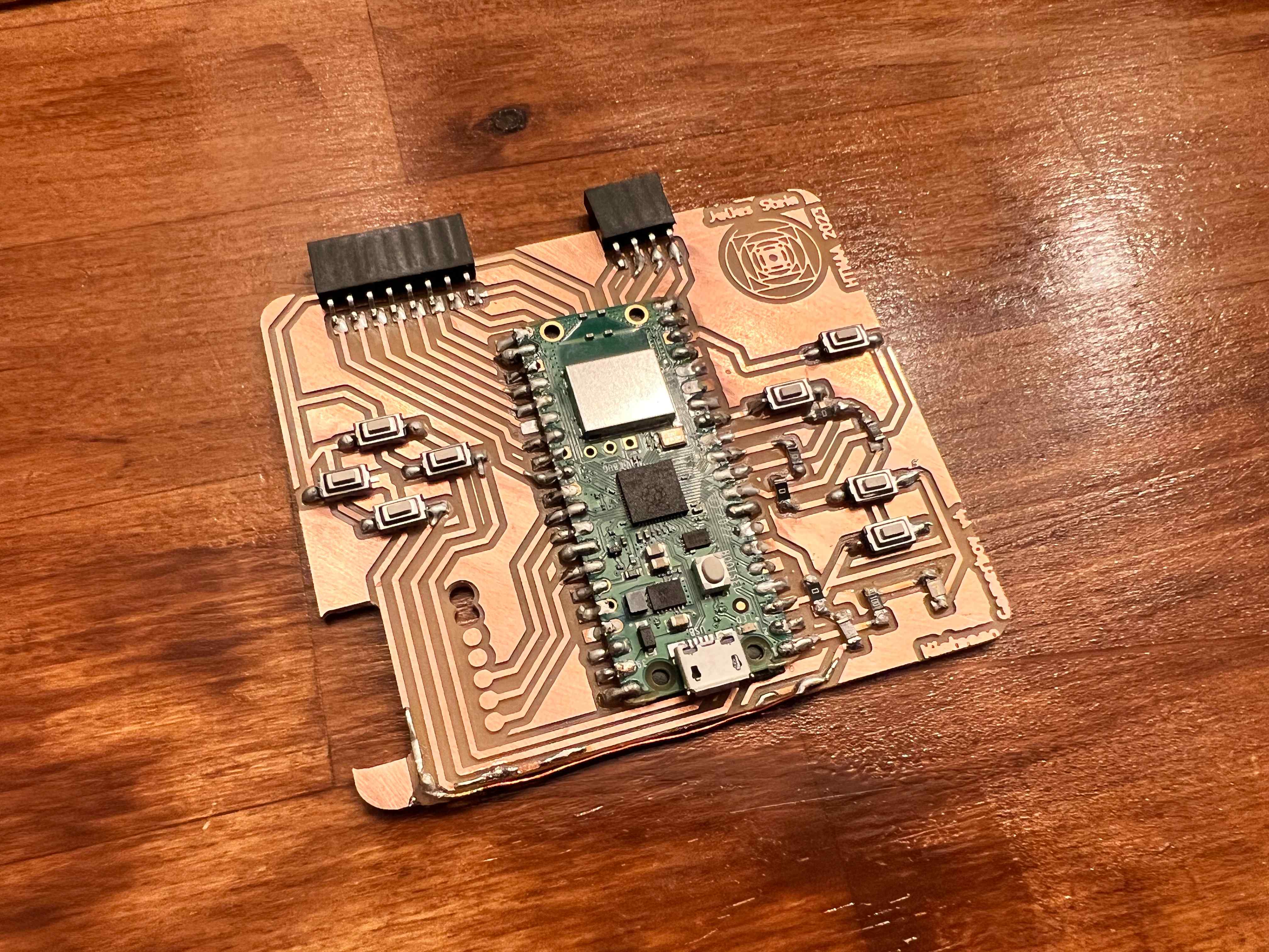
I have been working on this project for the past few weeks, and I have made significant progress. I have designed and printed a few different versions of the case, and I have also designed and milled a few different versions of the button board and a few different versions of a main board.


I have also been working on the software side of the project. I have been able to get the Pico to display a simple image on the screen, and I have also been able to get the buttons to work. I have not yet been able to get the screen to refresh quickly enough to display a video, but I am working on that now. I have also been able to get the Pico to read a micro SD card, and I have been able to get it to load ROMs from the card.


Next, I started working on versions of the case that could fit all three boards. The geometry of configuring the main board and the button board was relatively simple, but the video board was more difficult. I had to design a board that would allow the vertical screen to be mounted at an angle, and I also had to design a chasis that would hold the bezel in place which determined a fixed position for the board on which it was mounted.


I next started working on the integration of the three boards. The core board essentially aimed to remap the ports from the relevant side of the motherboard to the correct terminals on the pico. The button board was more complicated, and I had to design a board that would allow the buttons to be pressed about a half inch below the surface in order to make room for the metal buttons and their Holders. I also wanted to route the traces from the buttons to the pi in the order of the ports so that the boards could be connected without wires. but when I tested a version that used corresponding male and female horizontal headers, I found that the button board needed to move more than the motherboard allowed which would lead to the ports breaking over use, so I returned to using wires. I added some additional features like a power switch and potentiometer to control the volume, and I got a version working without any case, as seen below.


I continued my work on the chasis from where I had left it by adding ports for the battery switch, charge outputs, volume knob, and the start and select buttons which I had been ommiting until this point. I cut and printed several different iterations of the top panel and bottom chasis respectively until I had setled on a form factor that felt comfortable. I then began configuring the boards within the case, and found that I had to undo or change several of the features I had deisgned because I started with the chasis and then tried to fit the boards within it rather than starting with the boards and working backwards. I had to change the orientation of the power switch, the volume knob, and the charge ports, and I also had to add a small set of pegs to keep the boards from sliding around within the case.


I then began working on the buttons. I 3D printed a mold because the buttons did not rely on particularly delacate features, and then made an oomoo cast of the mold. I didnt like the feel of the corners of the buttons, so I milled a new mold with rounded corners and divets for the directional pad. I cast it in oomoo as well, making sure to get as many bubbles out as I could. I then cast the buttons in metal several times before producing a set that I was happy with. I found it very difficult to get the metal to cool without having bubbles in the bottom of the mold, and I also found that the mold wore out after about a dozen casts and had to be remade from oomoo. I printed plastic bases for the buttons so that the metal would not interact with any of the connective traces and so that they would sit snugly in front panel without falling through.


I then worked on getting the battery to both recieve charge from a USB-C port and to power the device. I found that this required stepping up the voltage to provide enough power to the screen, and I also found that the power controller that I was using was not well labelled. In connecting one of the traces, I somehow shorted the mainboard with 36 hours to go, and started again from the beginning. I was finally able to get the device working again with 4 hours to go until the presentation, and I worked on fitting it inside the chasis for the presentation up until the wire. The final result is shown below, broken out in different stages to highlight the different componenets.


