Week 8 - How to Input (almost) anything
Continuing with the input device that I worked on last week, I decided totry and make a single integrated board for my final project that would include the Pico W, the breakout for the screen and SD reader, the buttons, and the audio controller. I also wanted to include the terminals for the connection to the battery and the charging circuit, but I thought it better to get the board working first and then add those features.


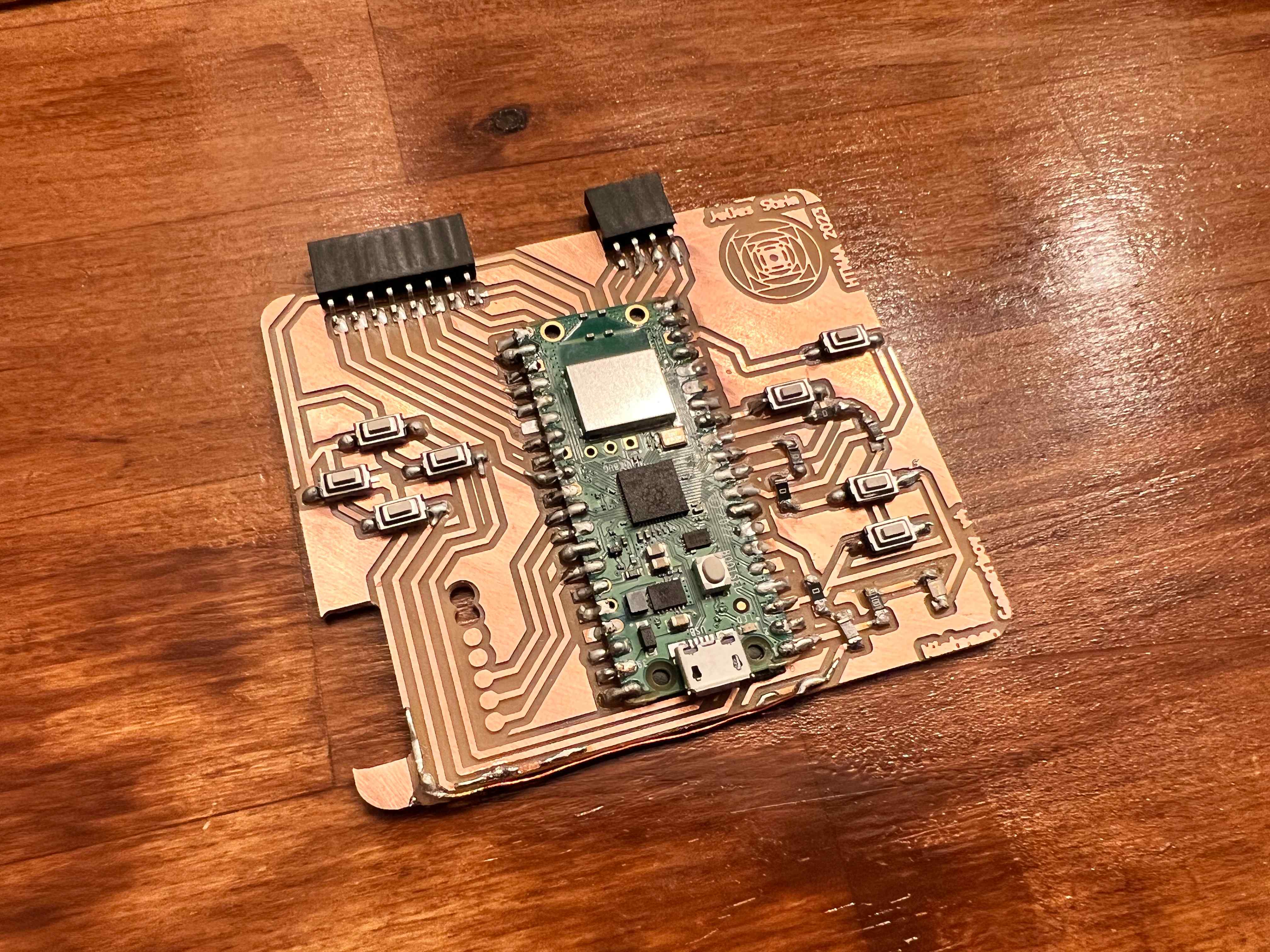
This board was helpful in that it allowed me to test the screen and the SD card reader, but the layout was nearly twice as tall and 50% wider than it needed to be. I also had to use a lot of jumper wires to connect the Pico W to the screen and SD card reader, which made the board increasingly unwieldy. I redesigned the circuit to be much smaller and to include the audio controller, but in doing so I needed to use nearly ten 0-ohm resistors to complete the circuit. I also did a duplicate board for which I used conductive paint instead of solder.


Besides being more difficult to work with, the electrical connections made with the conductive paint were not as reliable as those made with solder. I examined them under a microscope and found several spots where the paint was likely making accidental connections (first picture) or missing connections (second picture). In contrast to this the soldered board had no such issues (third picture).


Finally, to add a little bit of flourish to the project, I decided to try and make a custom symbol for the back of the board. I had often doodled a set of circumscribed squares that continued inwards, and I drew it in KiCad. I zoomed in under the microscope and also found that it was a good measue of the health of the endmill.
