Final Project
| Created | |
|---|---|
| Tags |
AI in the era of Pagers
What if Generative AI and LLMs existed during the mid 90s when pagers were around? I am now planning to build an AI-enabled pager. You could also think of it as a imagination of what the Humane AI pin would have looked like in the mid 90s.


It seems like there are many, many different kinds of pagers that have existed starting from the 1930s. Some only have one-way communication while others have two-way, some use RF radio while others use cell networks. One task is to figure out which exact model of pager/protocol I want to possibly emulate — as of now my eyes are on using the Motorola LX2 as a candidate.
The input and output for the pager -
- Mic so you can record audio and send audio messages (the esp32 sense camera already has an onboard mic so that works perfectly!
- Speaker so you can hear messages and AI response
- a nice LCD dot matrix screen to display messages and give that old-school pager vibe
- Buttons of course, to navigate in the device.
I’m planning to start with designing the board first and plan to design the enclosure (likely a compact rectangular-ish box) around the board.
I considered making the entire system run offline - without using any APIs. With this a core challenge will be running the LLM on the edge. Leo suggested I check out some work from the MIT HanLab — tinychat is a system to run LLAMA-2 on edge devices.

However, it runs on the NVIDIA Jetson Orin — a $500+ edge device which is far outside my budget. Hence for now, I’m going to design the device as internet-enabled and rely on APIs to run LLM queries. (On some more research I found the Jetson Orin is actually fairly large for my application at 11 x 11 x 7 cm.)
Since I need WiFi capabilities to use the GPT-4 API, I’m planning on either using a RP2040 with a WiFi module or a Xiao ESP32C3/S3. I could consider the RPi Pico but the board might be too large for my application.
Partlist
Since I’m using the ESP32S3 with the Sense expansion board, I won’t need to purchase a battery/power management IC (the xiao has one on-board) and I won’t need to buy a microphone (also on-board with the sense)
“Moodboard”
As a reference for my enclosure design and the interface (buttons etc) that I will need, I am using a few models as a reference in my “moodboard”


I likely want the same number of buttons as the visiplex model, but I will move the power button to the side and instead add an AI/record voice button to quickly take the user to the voice mode and start recording their command. At the same time, I think positioning the buttons like in the motorola device will be more ergonomic and I intend to add a hand grip on the sides like the model on the top right.
I also will design a clip to hook the device to your hip

I don’t intend my buttons to function like the one below though.

Designing the Switches
I’m debating whether I should add hardware debouncing since I will be using 5 switches and wondering if software debouncing will add a considerable number of clock cycles to the operation of my device. For now to keep it simple on the board design front I might stick with software debouncing. I found this helpful guide on hardware debouncing strategies though.

I revisited the xiao page on strapping pins though to make sure I’m not going to face any issues on reset if I use these pins as switch inputs.
Switch Layout
To understand how far apart the switches might need to be to match my desired interface and aesthetic, I placed out my parts in front of me and saw what worked best. I wanted the up-down buttons to be jammed against each other, and for this a 8mm gap between the leads seemed appropriate. Meanwhile the select button would be a little further, so 15mm seemed about right. Finally, the voice ai button was furthest to the right about 25mm from the select button.


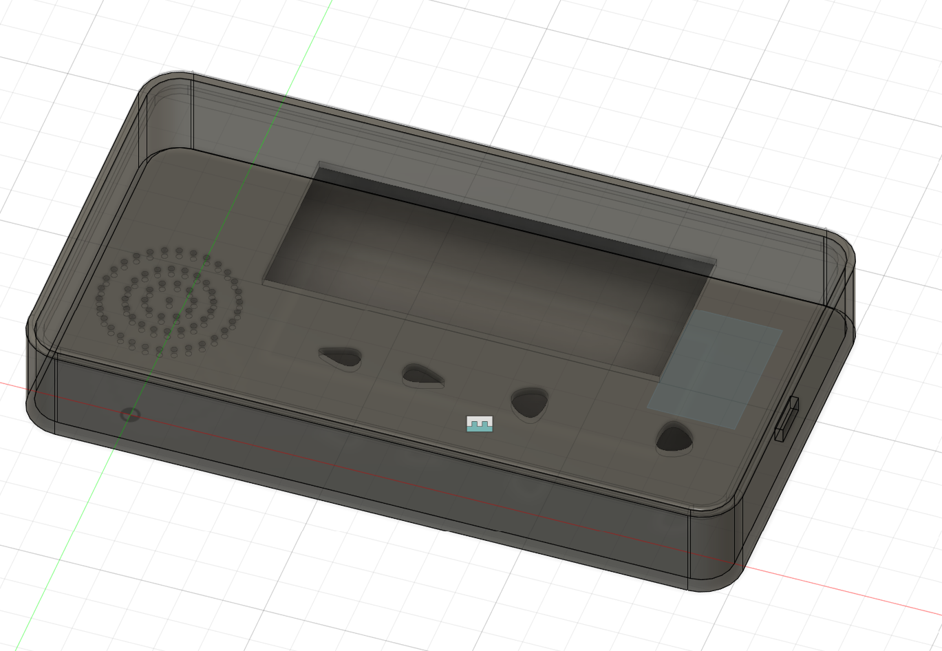
3D Modeling
Once I designed my PCB and knew it’s size, I could design the housing around the electronics to create my paging device.


Code Development
For code development, I largely used an article by Seeed Studios that detailed using the ESP32S3 for a speech to chatGPT application (link here)
I thought it would be pretty straightforward to get this up and running but I faced an innumerable amount of bugs in getting the code to work. First, dynamic memory allocation was failing on my device. After a few hours of digging, I realized this was because the PSRAM was disabled in the Arduino IDE (which is not expected or standard) and had to be manually enabled for me (🫤). Why this would even be disabled by default in arduino is beyond me!


I also ran a local Node.js server on my laptop that received speech data as a wav file through a HTTP POST request and then pushed the file to Google Cloud’s Speech-To-Text service and sent the resultant text transcription to my ESP32S3 through a
Finally after fixing that and 20 other bugs, I was at a point where I could get the ESP32 to record my voice, send the data to my local Nodejs server, and receive the transcript back with which it could then query the OpenAI API.

LCD Programming
No pager is complete without it’s digital interface - the trusty green LCD. I picked a 20x4 LCD for this purpose. I used the LiquidCrystal_I2C arduino library to interface with it, and then later wrapped this around the LiquidMenu library to build multiple menu systems that can be switched between.

I created a menu system that included a welcome screen, a home screen with a main menu, and certain submenus to show the recording state and GPT response.


Final Product Integration
Functioning
The last recorded evidence of how far I got is below. I did in the end manage to get the device to also display the ChatGPT response on the screen, but that was not recorded.
Enclosure

Closing Thoughts
I definitely want to keep working on this. Through this project, I got to learn a lot about creating a complete product since I tried focusing on enclosure design and integration as early as project. I got to learn a lot about using CAD tools and got a ton of reps in with EDA tools and production through the project which will stick with me forever.
Over the next month, I hope to add a text to speech synthesizer so that the device takes speech not only as an input but also responds with speech. I also want to move the API requests to the speech to text API onto the ESP32 instead of doing it on a local node.js server. I think there’s also a lot of potential to miniaturize the device further, so I also look forward to redesigning the enclosure and electronics architecture.