Measure something: add a sensor to a microcontroller board
that you have designed and read it.
Step 1: Design
The Design
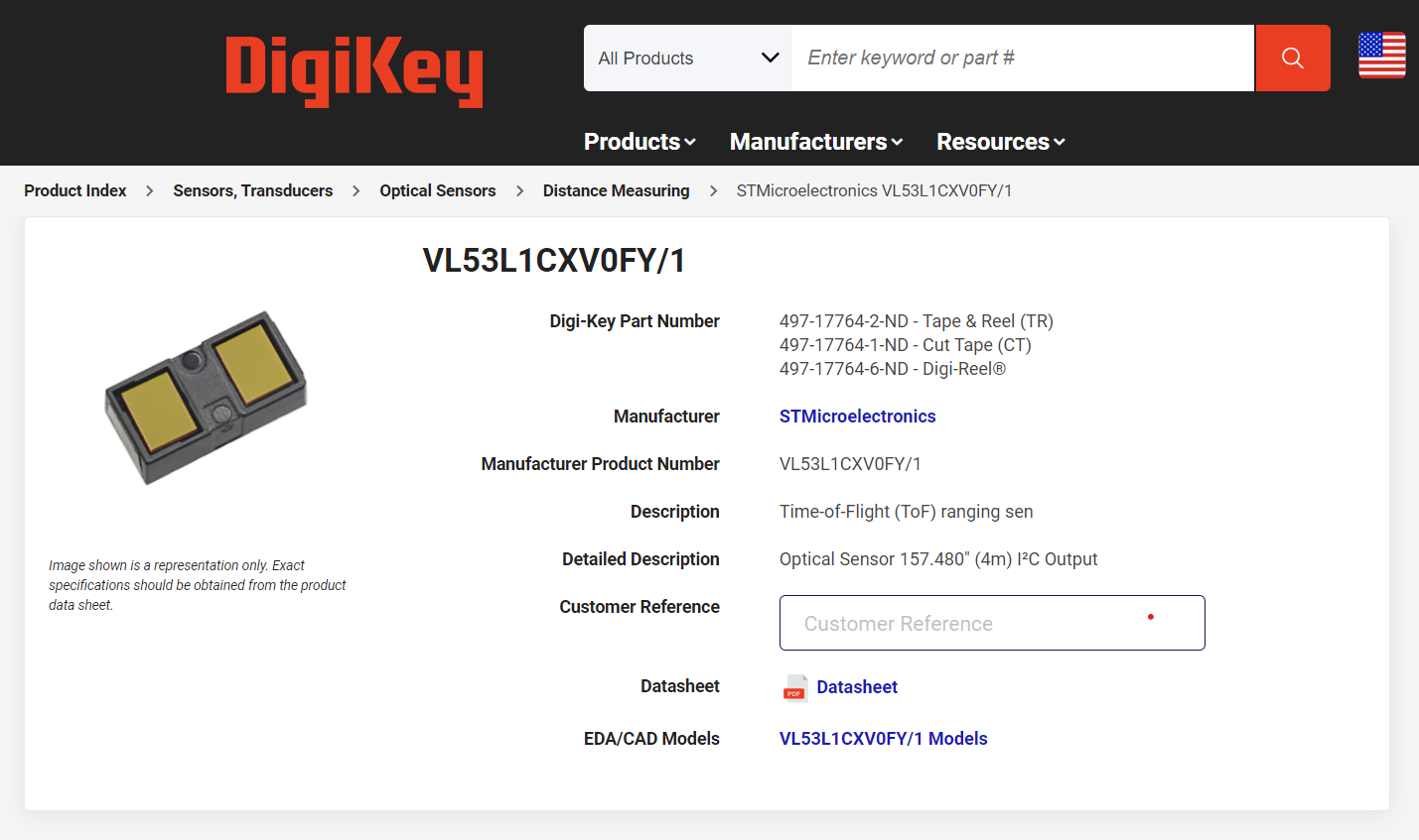
So for this week I wanted to try out one of the distance sensors. This is the VL53L1CXVOFY/1, what a memorable name. It's a Time of Flight sensor (ToF), which means that it sends a pulse of light of a particular wavelength, it flys though the space, reflects off a surface, and is received back (this is why it has two rectangular screens on top, one for projection one for reception). It compares the period of the sent and received wavelength, and can use the lag between them to calculate how far the light must've traveled in the space. If you check the datasheet it says this particular component works for up to 2m, which isn't terrible far but its like a $5 piece so I mean you get what you pay for.
The Fab Inventory
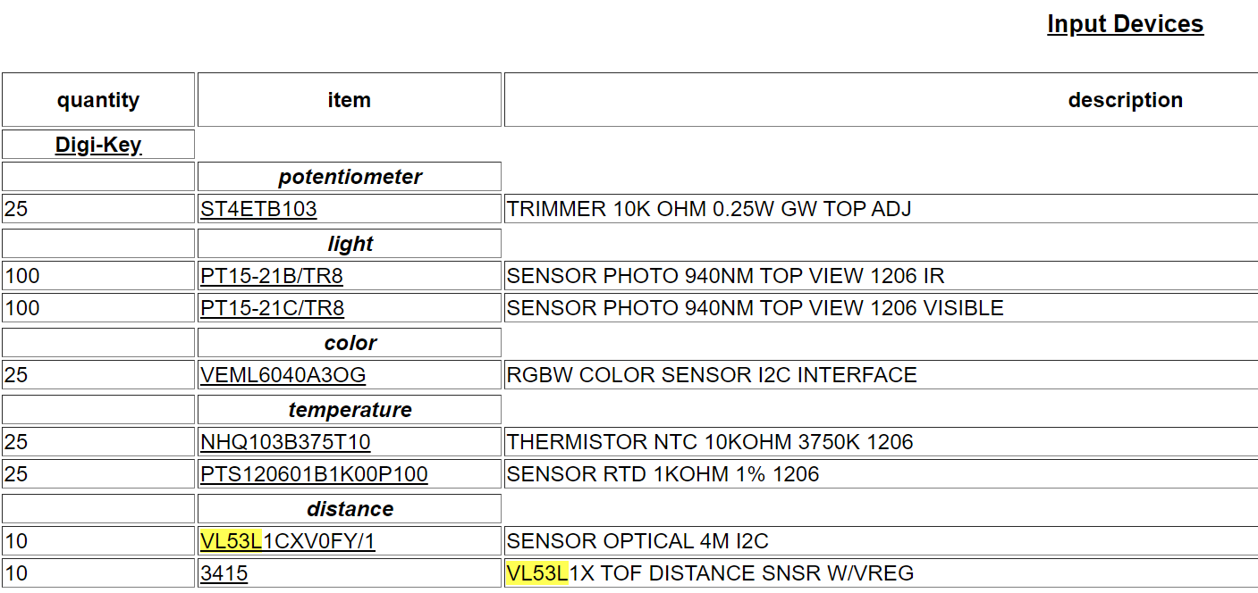
I quickly checked to see if we had it in stock in the Fab Lab inventory, in the clear.
The Datasheet
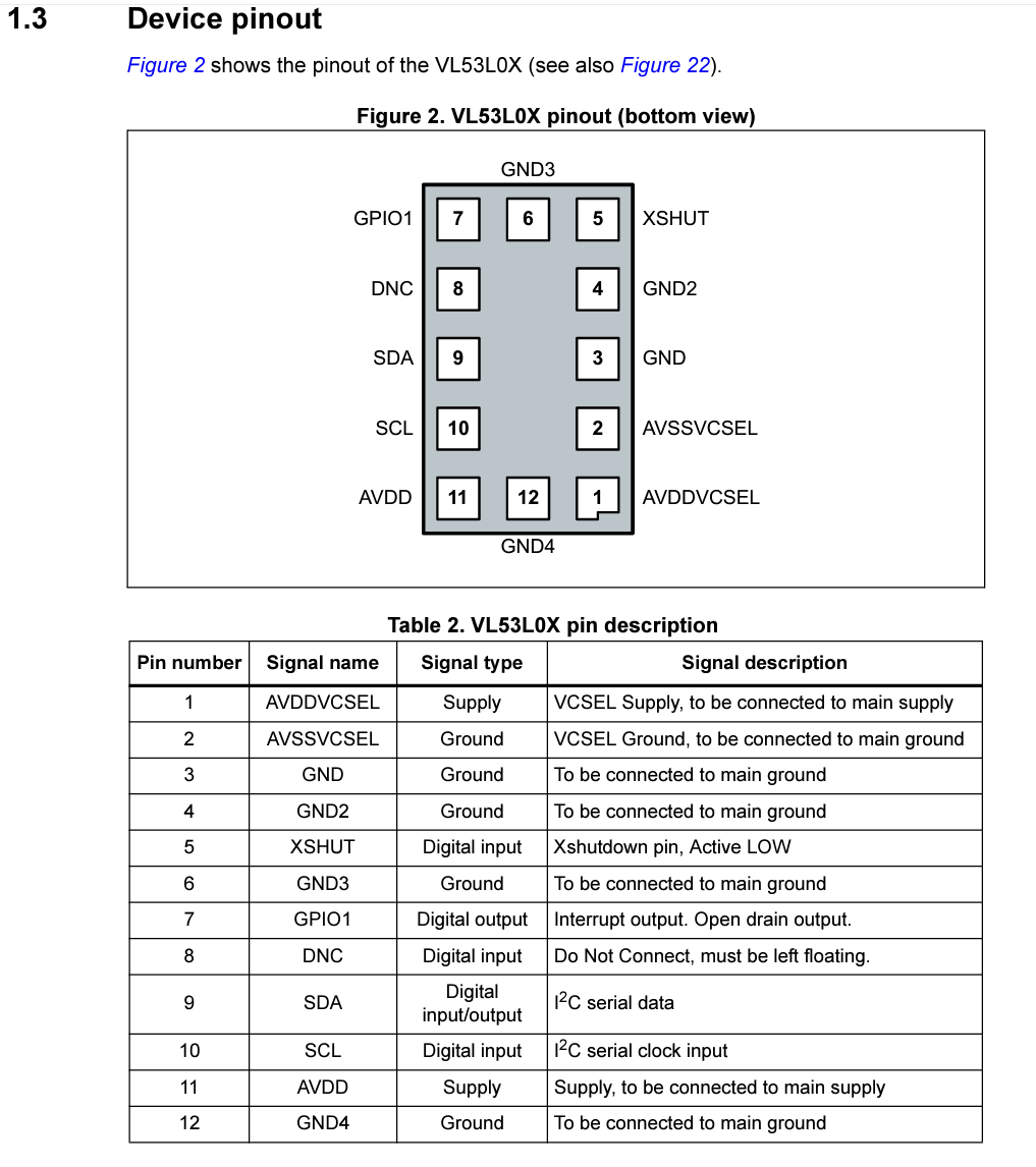
In the datasheet you can see that this small part, about the size of a grain of rice I would come to find out (-.-) , has twelve pins. The all have acryonyms, many of which I have no idea about. I recognize that there are 4 grounds, and thats about it. But they give a pin description, which was a good place to start wrapping my head around it.
The Schematic
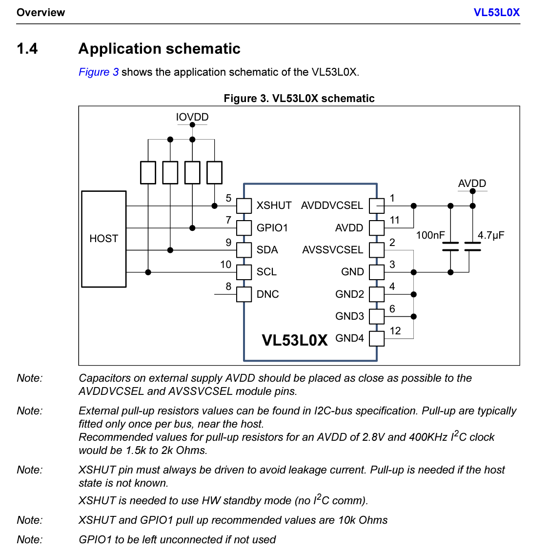
Here was another diagram shown in the datasheet. This is an application schematic, and its helpful because it shows that AVDDVCSEL and AVDD both just attach to the powersource, with capacitors close by, and that AVSSVCSEL is simply another ground connection. DNC is left unconnected, and the rest all have pullup resistors. This was very useful.
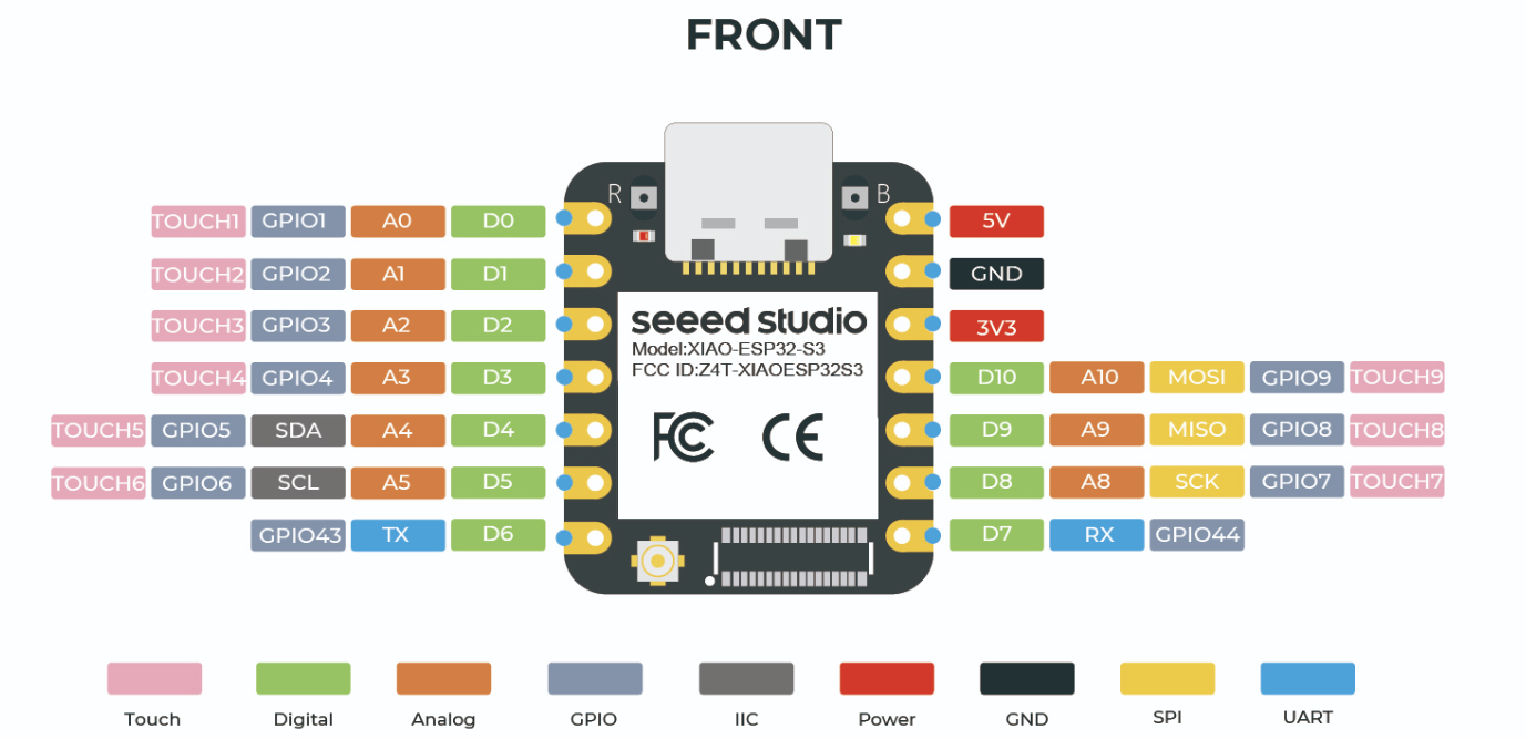
XIAO ESP32 - S3
I wanted to cross reference this with the pin breakout of the microcontroller I wanted to use. I choose the XIAO ESP32-S3 because there was also something that I wanted to do with a camera, after setting up this ToF sensor. I notice that D4 and D5 have an SDA and SCL label, both of which show up on the schematic diagram. Will have to make sure to have these correspond in the PCB design.
Neil's VL53L0X Board
This is not for the VL53L1CXVOFY/1, but rather the VL53L0X. Turns out it doesn't matter because if you look at their datasheets they have the same pin breakout. This one I am using actually has up to 4m distance measurements, while this one has 2m.
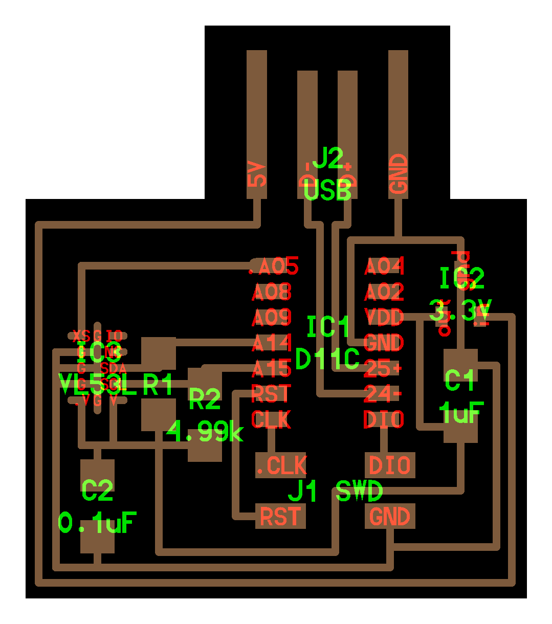
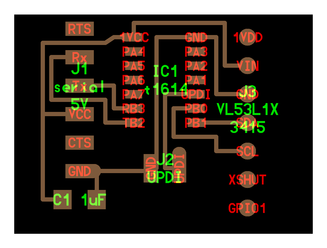
Neil's VL53L1X Board
There was also this board diagram in Neil's links, but the component didn't have the same footprint (righthand side). I looked up to see if I could find this footprint online, and I found that this is for the VL53L1X Polulu, which is a little breakout board that you can buy that would ultimately make it a lot easier to solder on. I would like to do this, but these aren't in stock, and are $20. I figured to try the small piece since it was on-hand. Upon second look I actually see that xshut isn't connected on this, which means I probably didn't have to connect it either (I did). The only things connecting to this polulu module are data-in, data-out, power and ground. That is straightforward enough.
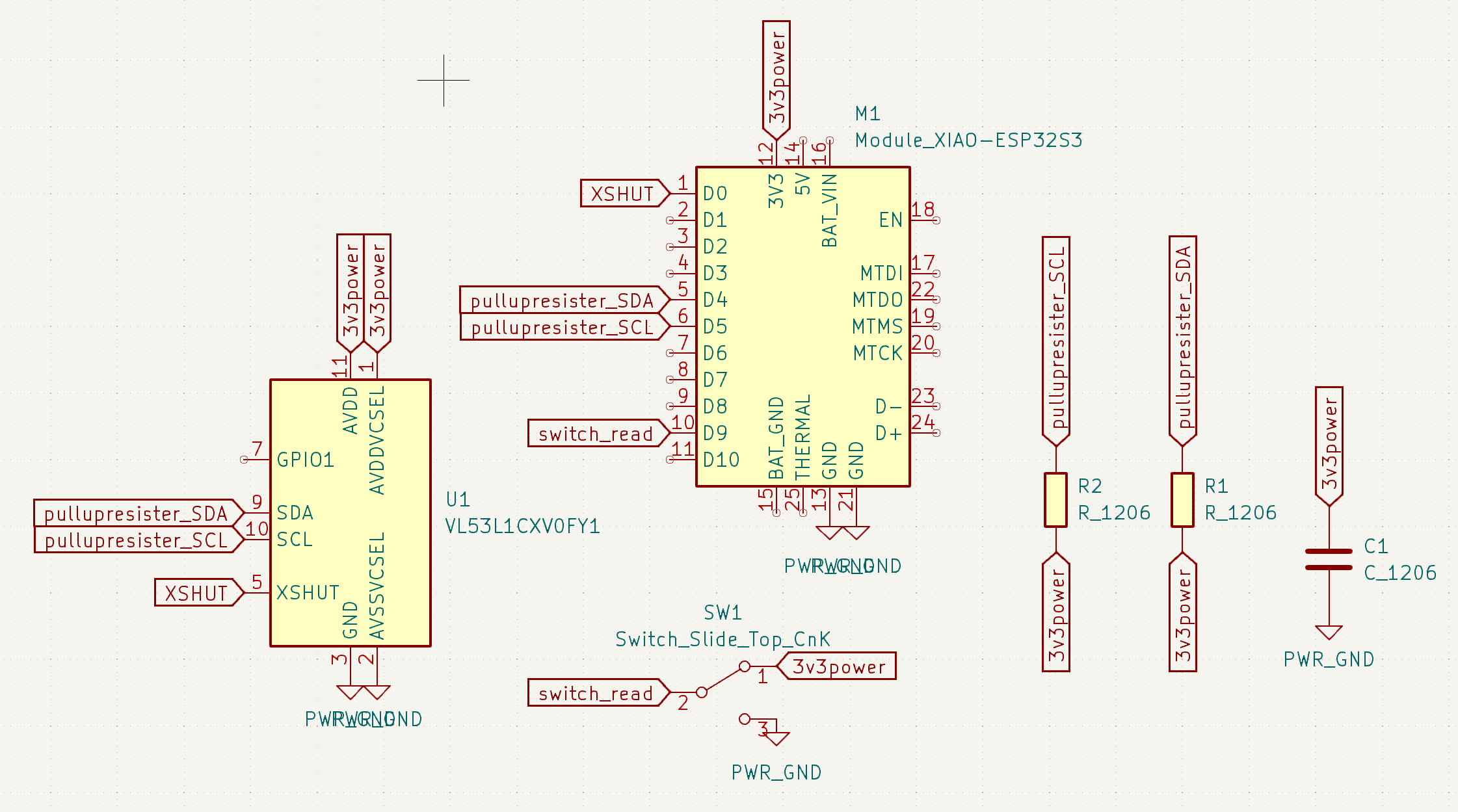
Design Schematic
This is the schematic I came up with. I ended splitting it up across some connector pieces because it would ultimately make it easier to test. As mentioned I think could've left XSHUT unattached. I added a switch to the board too. It's not a power switch, since the flow isn't determined by whether or not its letting things through, but it is attached to a pin which could then get read by the microcontroller to turn the ToF datastream on/off on the software side of things. Since the XIAO will just be plugged into the wall and the power will be around until I simply unplug it, this approach makes more sense.
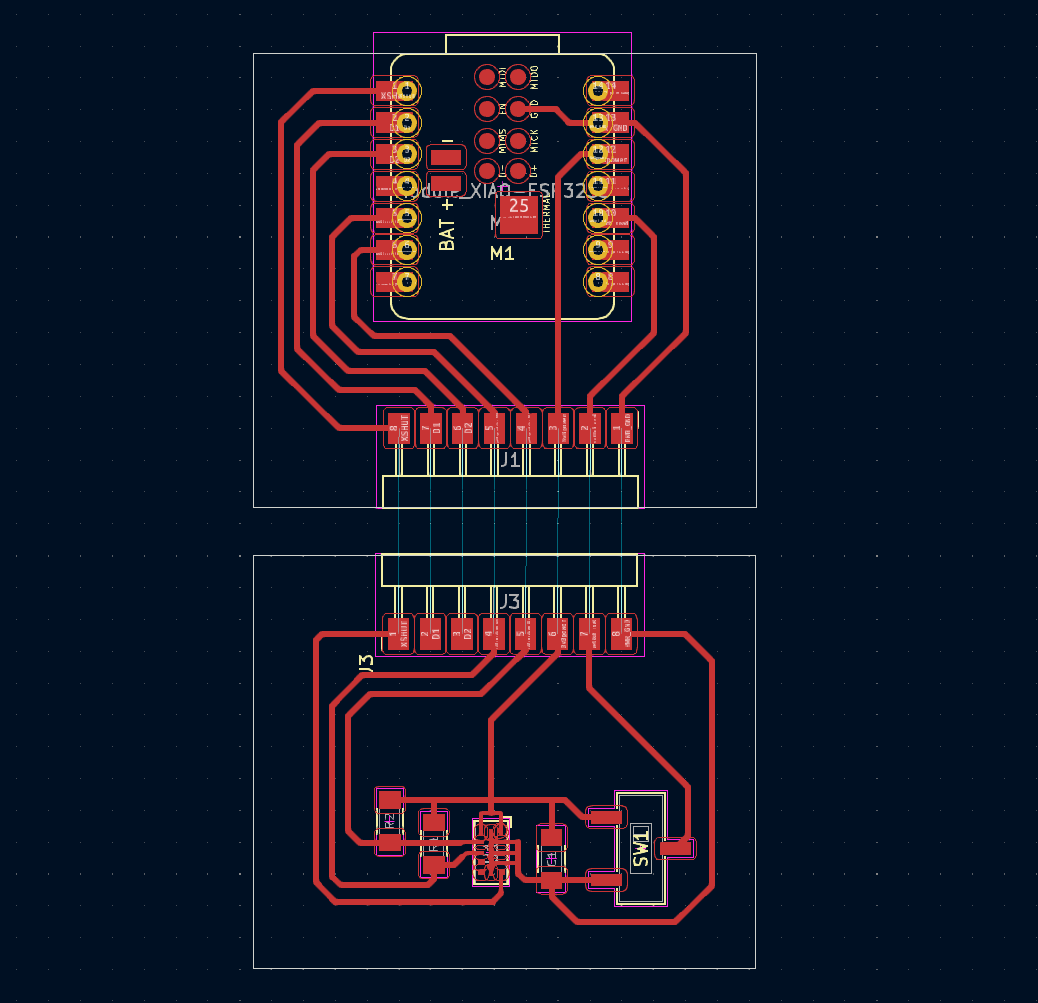
PCB Design
Here is the PCB design. I added two additional pin breakouts on the left because who knows, but they're not really doing anything atm. The ToF sensor works on a 3.3 V powersource, so I'm using that pin output on the XIAO as my power source. There is a pullup resistor for each of data-in and data-out, and a capacitor "as close to the sensor as possible".
Step 2: Fabricate
So the lab didn't have any paste, which I think it probably what I needed to use in order to do this, but I tried to see if I could just pre-solder the pin areas with regular solder being careful and then try to place the ToF sensor on top using tweezers once the solder started to reflow. This was my pre-solder.
Placed on the hotplate. I started with 300 degrees. When that didn't work I went up to 350, then 400, then lastly 450. Nothing really caused the solder to reheat enough.
Lastly I tried to see if I could use the hotair gun to heat the solder underneath the sensor, but I ended up melting the sensor RIP (╥﹏╥) I'm thinking there must be a better technique that either involves the solder paste or an oven. Want to figure this out this week and use this board for outputs.
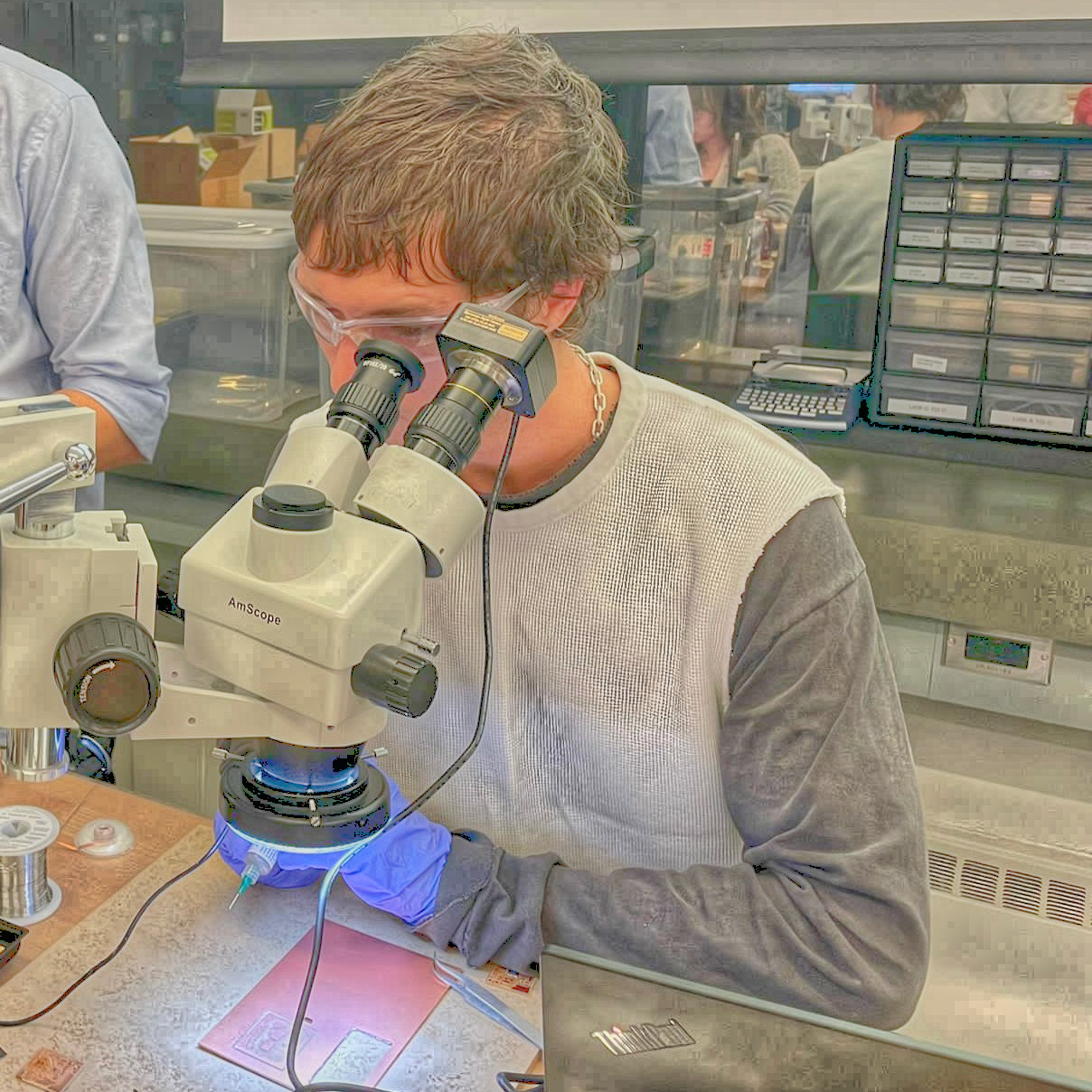
Me cosplaying as a scientist
When in doubt, ask an expert. I went to Anthony's office hours to learn how to best solder tiny pieces. Firstly, he recommended that for a piece this big, to just buy the breakout board. I probably would've just done this, I didn't really know what I was getting myself into frankly, but after I was in there was no turning back. So, if you want to solder on a piece the size of a grain of rice that has twelve individual pads, you start with solder paste.
Live Studio Audience
It was a real show. You can see im using the syringe of solder paste under a microscope projection. You can expect the amount of solder to be less than the paste, because the paste simply consists of spheres of solder in a flux matrix, and therefore the volume of the paste is limited to the spherical packing density of the solder bits. Once heated, the flux runs off and the spheres fuse. So you can afford to be a bit more liberal with how much paste you lay down, and if it's done right, the heat will simply reroute it to coalesce around the pads.
Once you lay down the paste, carefully orient your component atop using tweezers. You set a heatgun to 270C if you wanna go low and slow, or 300C if you wanna go high and fast. Look closely during this and hold the gun about .75-1 inch away from your component. The paste will go through two phases. The first phase, it will start to move, you will probably notice you component shake a bit, this is when the reaction is starting to occur. There is a second phase when the solder actually melts, and if it happens correctly, your piece will move perfectly to the place which it is supposed to sit due to the heat transfer properties, and everything will bind correctly. How do you test this? Well considering all the bads are underneath and there is no way of looking at the solder connections, there is no way of knowing outside of actually just testing to see if you board works. We did use a multimeter to see if the ground line was connected to the power line, which it wasn't, so while we don't know if it works yet, we know that that isn't an issue.
After the solder melted the piece oriented orthogonally so I take that as a good sign, fingers crossed!
Moving on to attaching the rest of the components, I grab a switch and notice that the pads are stretched quite far out from the switches pins and there is metal underneath the switch that these pins are likely touching. I don't want this to cause a short.
I cut out some electrical tape to try and bandage this potential. I think with enough solder I can still make a connection I just don't want it shorting out the board in the process.
I'm waiting on attaching a capacitor because while my lab has 6 differently rated capacitors stocked, 5 of them offer less capacitance than this board is speced for, and the one other one offers 100x more. My guesse is that it's okay to oversize, but I want to double-check on this before soldering it down.