How to (almost) Make (almost) Something that (almost) Makes (almost) Anything
Cedric-Pascal Sommer's Class Page
MAS.865 2024
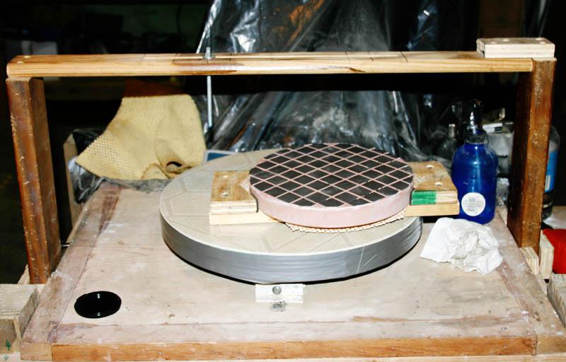
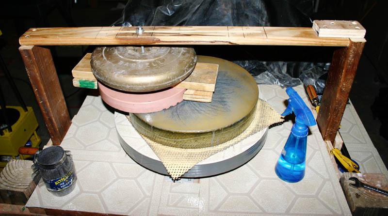
I will be working on an open-source lens making bot, the first of its kind actually. I’m big into optics, particularly for astronomy and astrophotography. Now this is a hobby where you can easily spend the same amount of money on a good refractor telescope as on a car. So far, optics remains one of the most inaccessible and least prototypable „things". I do grind mirrors for my own telescopes by hand for fun (just like Newton - still the best way to go about it), but it’s damn near impossible to do this on the scale of large mirrors or small lenses - let alone multiple lenses. There’s a few folks out on the internet who really push it with their own DIY optics shop (like this) and I believe it should be possible to simplify all of the processes for lens making into one modular machine that can be converted and adapted for different needs. I know it’ll be a steep learning curve, but I hope this is a long-term project that will open up a ton of high-precision optics-based instruments and machines to prototypists all around.
Components
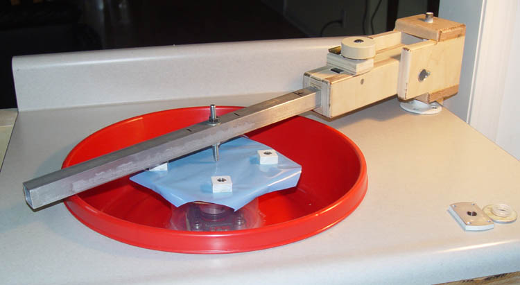
Turntable
- A simple turntable to mount the glass sample onto. Could also be usable for other spin-based operations (clay working, ...)
- V1: Simple turntable at constant speed
- V2: Simple turntable at variable speed
- V3: NC turntable
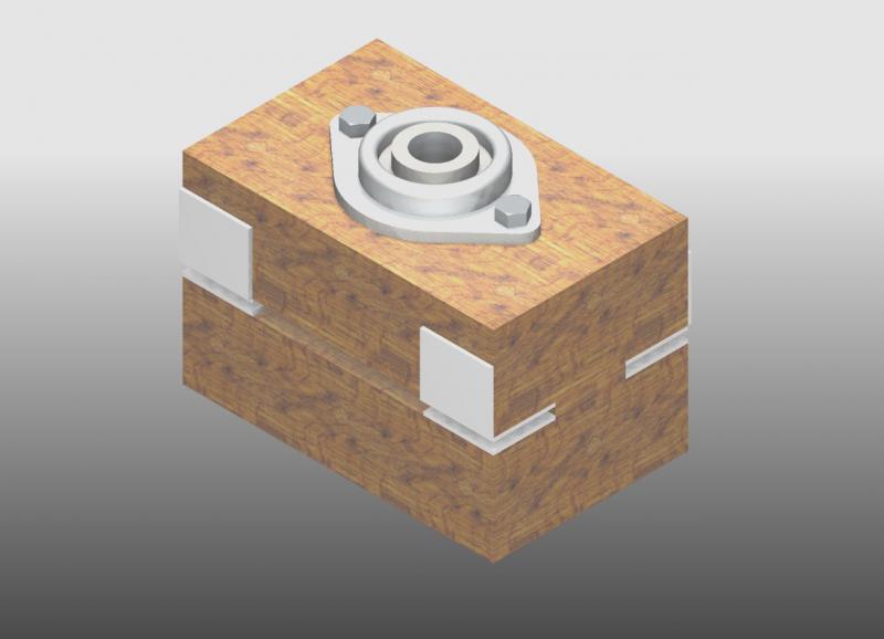
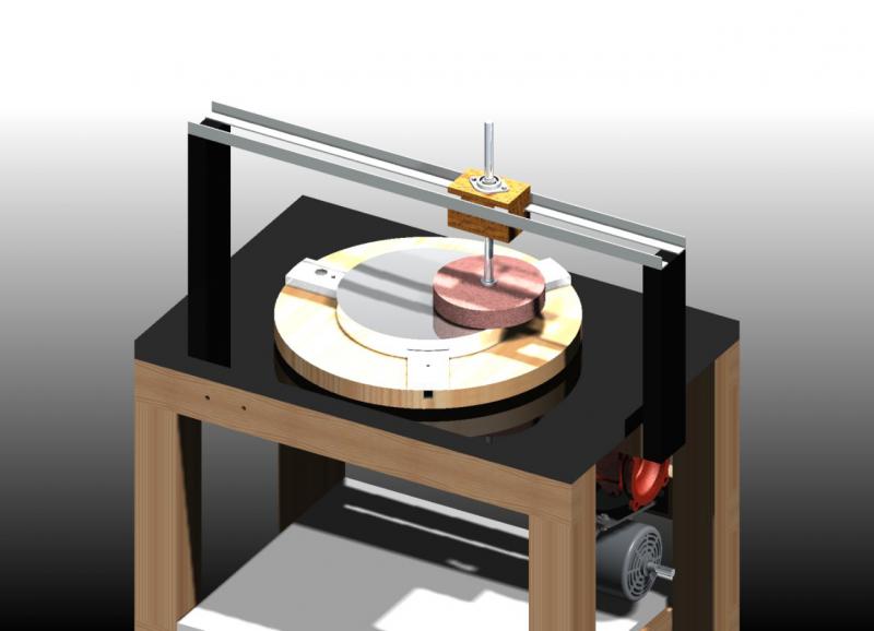
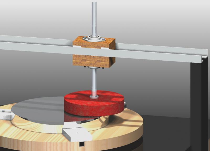
Stroker Arm Mechanism
- V1: Maybe first just a fixed post spin grinding machine, that adjusts the offset of the tool
- V2: The stroker arm mechanism is another mechanism, I guess? For a single arm stroker?
- V3: And then the W (Zeiss) two stroker design?
Grit Applicator
- Something that spits out grit and water to continue grinding
Path Planning & Simulation
- Enable different path planning and simulations of the grinding operation and lens shape
- We want to end up somewhere where we input the lens shape we desire and then run on machine
Other Notes
- How do we make it adjustable from lens making to mirror making?
- Can we make it closed-loop?
- Can we add metrology to make sure we are getting a consistent shape?
- But then how do we add NC? Like the ability to control different grits and water spray maybe? And the ability to adjust the stroking mechanism, like the offsets etc and knowing what type of lens they will create could be very interesting...maybe a hydraulic arm that can be shifted in its offset. Or a linear actuator...
- CoreRad (being able to reach any point in radian / polar coordinates, rather than Cartesian CoreXY) with a fixed motor
Systems Design & Engineering
Frame
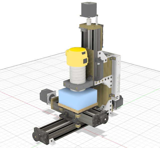
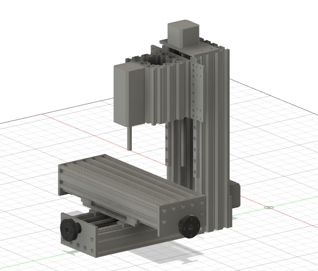
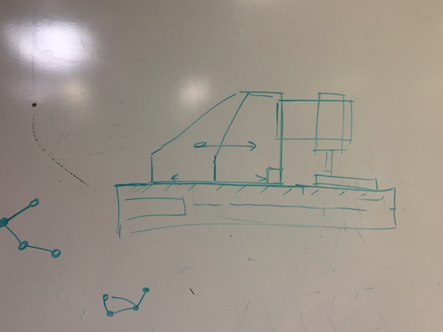
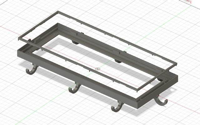
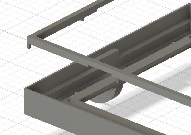
I started looking for a suitable systems design frame to base my design on. After looking through multiple projects of past years, hackathons, and other open-source files, I came across a small desktop-sized mill with a design that seems almost perfect for what I need: The OpenBuilds MiniMill. Unfortunately, the Sketch file is rather messed up in Fusion and hard to edit, so I took some time to clean up the design and change some of the components (motors, the lead screws). Next step is to add the 4th axis to allow for the tool to be held at an angle at the machine.


Library of Machines
Mirror-o-Magic
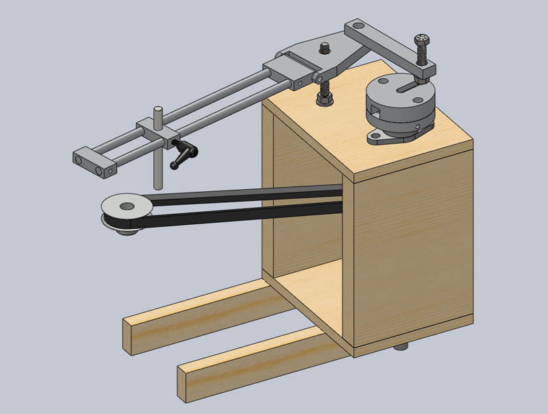


Zeiss Grinding & Others
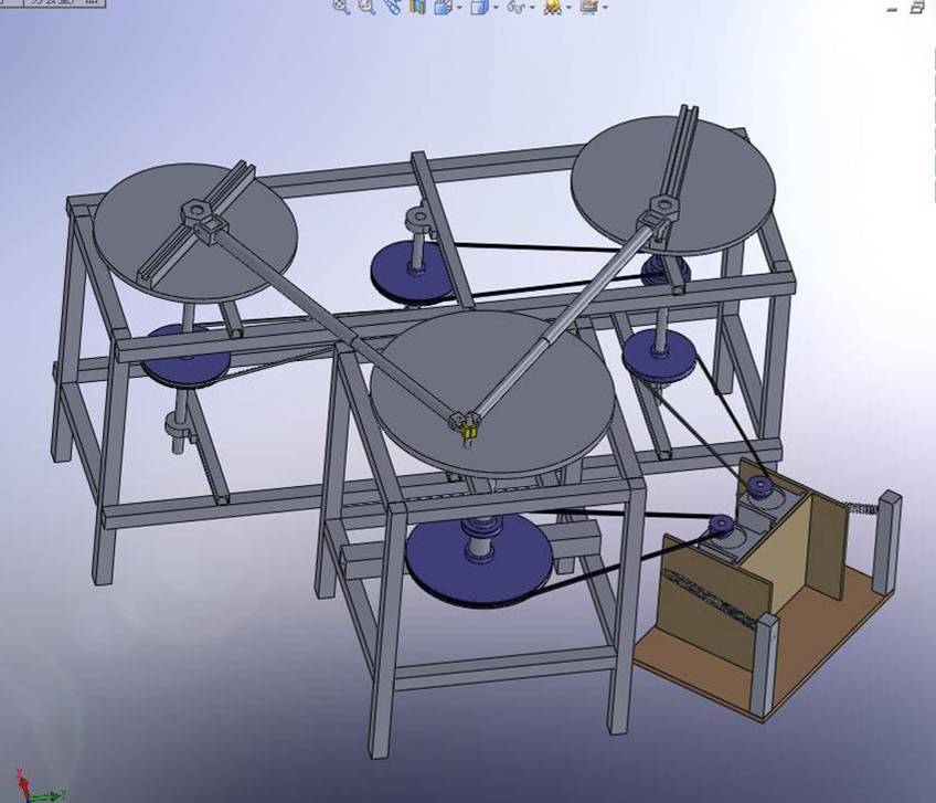

Other home-made stuff
References
- This guy made his entire lens with housing from scratch
- This guy makes lenses from sand and rocks
- Making telescope lenses at home by hand
- Optical lens making in 1600s for microscope lenses by Corning Museum of Glass
- Making lenses on the CNC router
- Camera lens making in Japan, beautiful overview documentary over the entire process
- Doing it from acrylic
- Zeiss grinding machine
- Interesting monolithic mini telescope lens, just to show a more advanced version of what you can make out of glass
- Making eye glasses in rural India - yes, simple physics allows for the making of extremely high-precision optics. Similar to Dobson
- Classic John Dobson video on telescope making
Prototyping Components
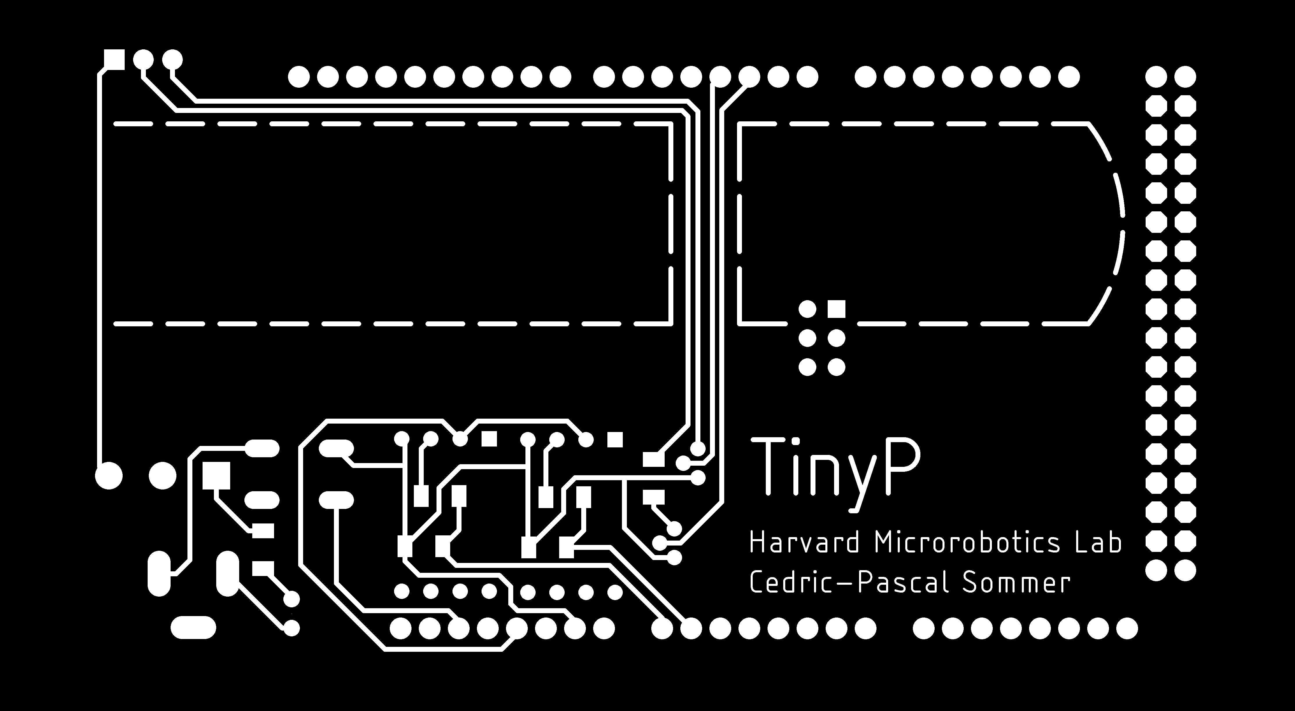
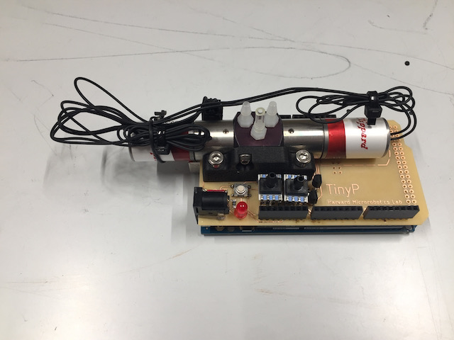
This week, I worked on a prototype for the Arduino pressure controller shield I want to build. Basically, the idea for this pressure controller is to be a plug-and-play controller board that sits on top of an Arduino Mega board and allows for an easily modifiable setup of different valves and sensors to accomodate simple pneumatic and vacuum setups for applications like soft robotics.
Prior Art
I am building this project on the basis of a few fully-integrated systems that come pre-built to allow for easier modification of the system and a way to test different valves and sensors. The control firmware will be based on CTRL+P by Clark Teeple.
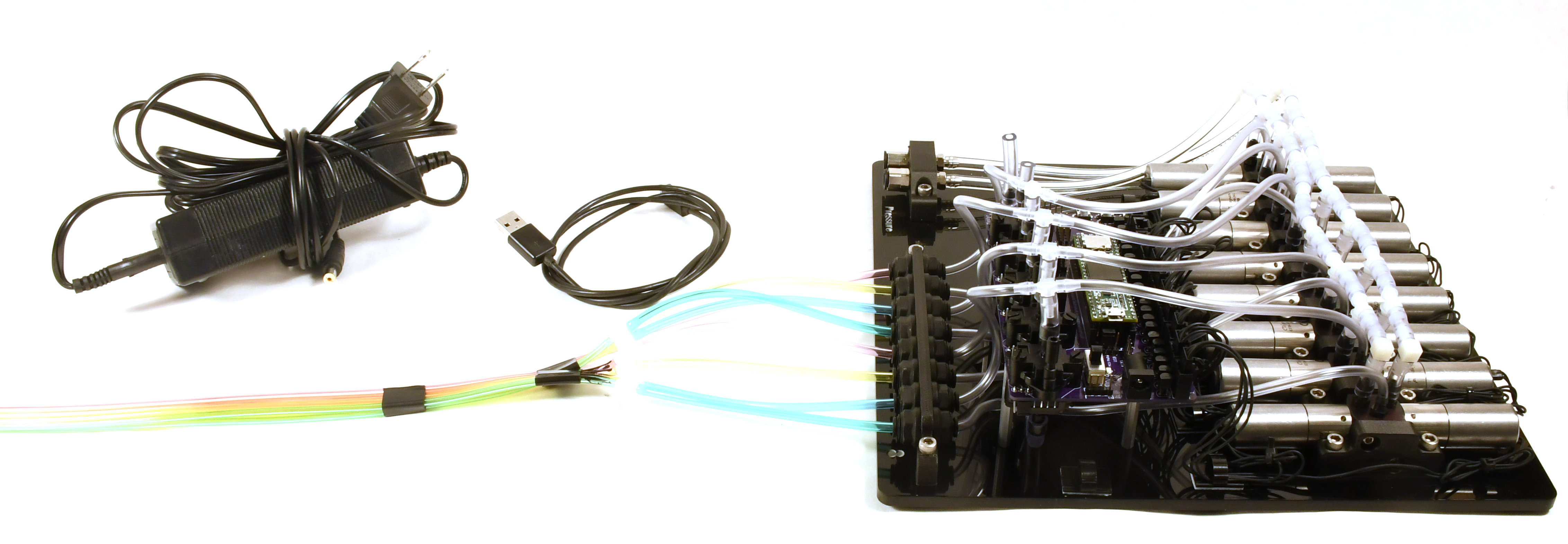
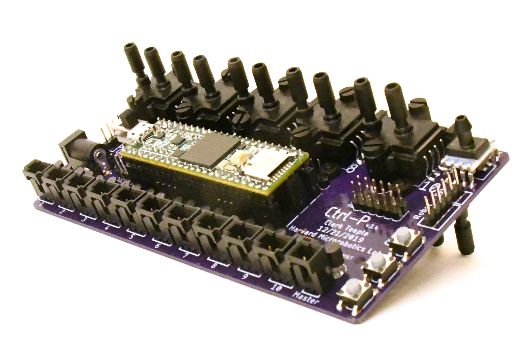
The CTRL+P pressure manifold developed by Clark Teeple that allows for up to 8 channels, using some continuous-modulation valves for low-pressure pneumatic applications

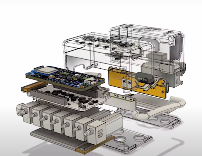
The FlowIO platform by Ali Shtarbanov, Hyejun Youn, Ozgun Afsar, Joseph Paradiso of Media Lab. Again, a great general purpose, fully-integrated system. However, I want to open this system up for more modular expansion and modification
Hacky Prototype
In order to figure out what functionality I need to make my shield both as flexible as possible and still provide common functionality for pneumatic control, I just took a box full of old weird undocumented pressure-application equipment from our lab (pumps, valves, tanks, pressure sensors, flow rate sensors, and anything in between and beyond) and tried to interface it with an Arduino Uno.
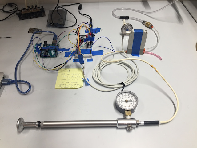
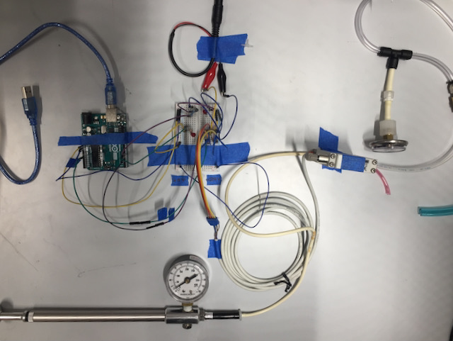
Granted, a lot of the components' documentation is hard for me to understand and the existing platforms might not be ideal for interfacing them - but this is exactly the challenge I am trying to solve. So I went ahead and just built the pressure and electronics circuit around it. While the result looks absolutely hacky, it helped me isolate what elements I need to integrate on my board to provide the basic framework for building something like this in an integrated way.
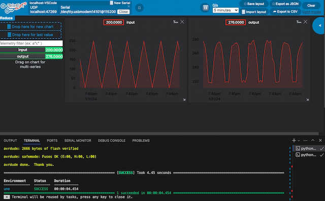
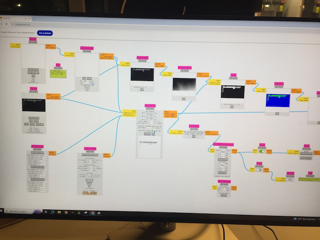
Once I got everything to work, I used PlatformIO in Visual Studio to run some basic operation of actuating a single valve and plotting the measured pressure in the pressure chamber attached to the valve. In the following pictures, I am sending different input values over PWM to the valves.
WTF is going on?
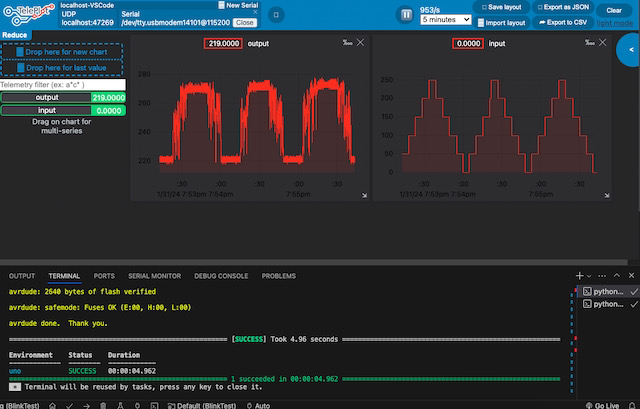
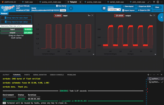
As I tried modulating the valve along a linear pressure trajecory using PWM, you know, easy peasy stuff, I noticed that I couldn't get it to follow the trajecory consistently. The valve seemed to either stick open or closed, and if I sent a voltage in between, it erratically opened and closed. Notice the comforting sound in the video that definitely does not sound like a happy valve.
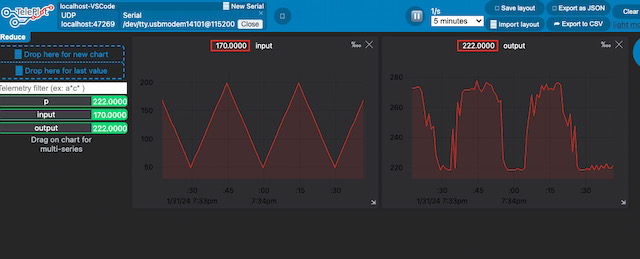
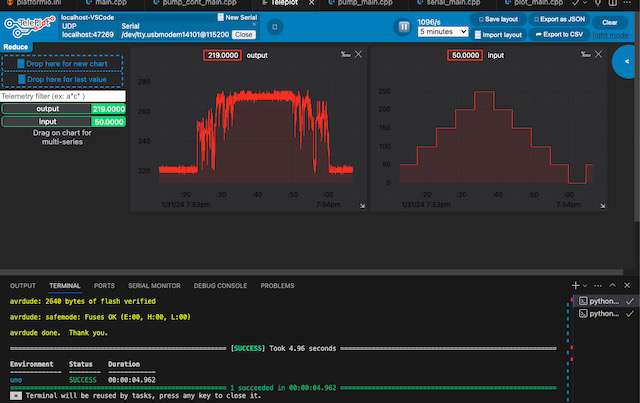
Now this is how I found out how these valves actually work. If you know anything about pressure applications and specifically how valves work, you probably already know this, but for a simple valve, there is usually a simple solenoid inside that either lets pressurized air pass in or out of the system.


So did I just try actuating a solenoid using PWM, hoping that it would be able to maintain an intermediary stage? But wait! The specific valve I was playing with was actually rated for continuous modulation! Which means that they are built with two solenoids! So why am I not able to continously modulate the pressure?
At this point, I have a few theories. Theory 1 is that I actually may need a real analog-to-digital converter, because the PWM signal might not work with these valves opposed to a true analog signal. Theory 2 is that maybe my pressure chamber is so small (just a hose) that it can't work. I'm still working on finding out
Component Updates
Modular Pneumatic Manifold
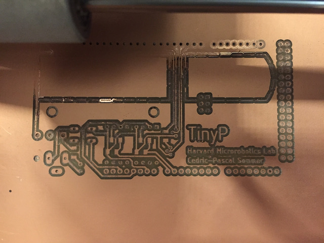
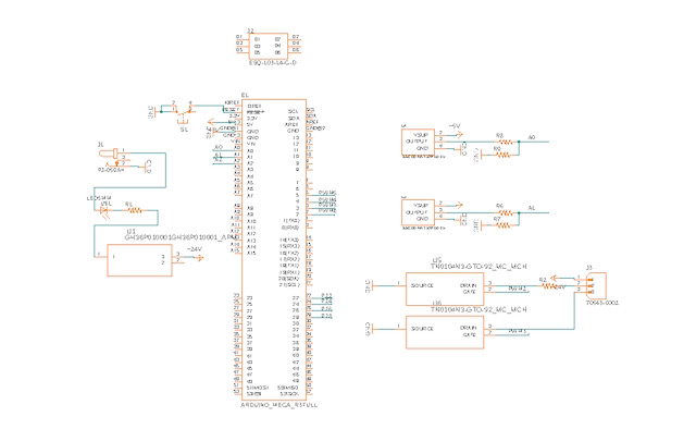
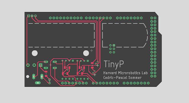
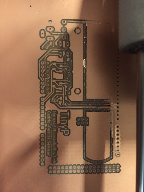
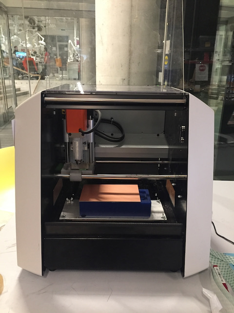
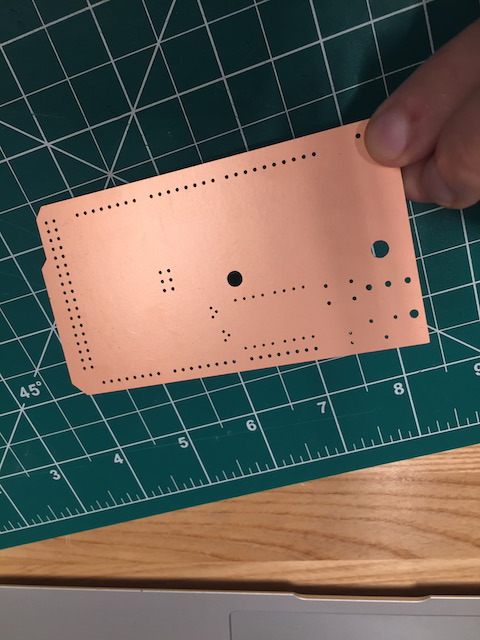
This week, I workers on the electronics for the pneumatic manifold. As the goal of the project is to have a modular and versatile controller that works with a variety of valves, pumps, and sensors, I wanted to build it on top of a widely available board. Luckily, I came across an open-source firmware for a multi-channel pressure controller in C that someone had built in the past. Going from the specifications, the firmware is optimized for the Teensy 3.5 and the Arduino Mega 2560 R3. As I happened to have a Mega lying around, and as it’s pretty widely spread amongst beginners, I am assuming this as the basis for my build. I started by importing the part into my design and then drew out the schematics of all the components. Basically, my shield will have space to mount one valve with up to two channels (enabling continuous-control valves with a pressure and a vent channel) and one sensor, enabling full continuous pressure control in one output. The valve can be modulated over PWM, the sensor value can be read as an analog signal. After finishing the design of my PCB, I started milling the board on the Roland SRM-20, traces on the 1/64 mill and outlines on the 1/32 carbide mill. Unfortunately, our lab lost the sacrificial plate somehow and I had trouble machining the traces accurately. I will stuff the board by next week and run it with the firmware I found online.
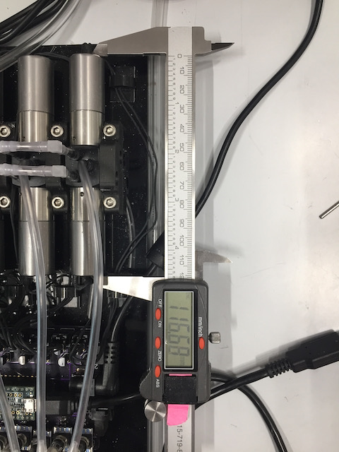
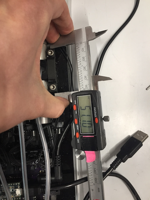
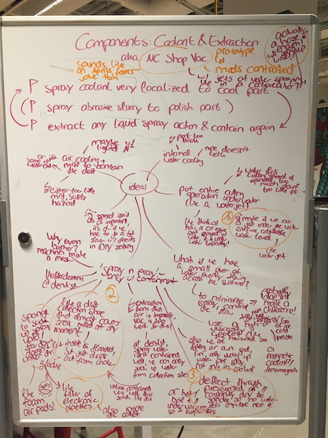
NC Shop Vac
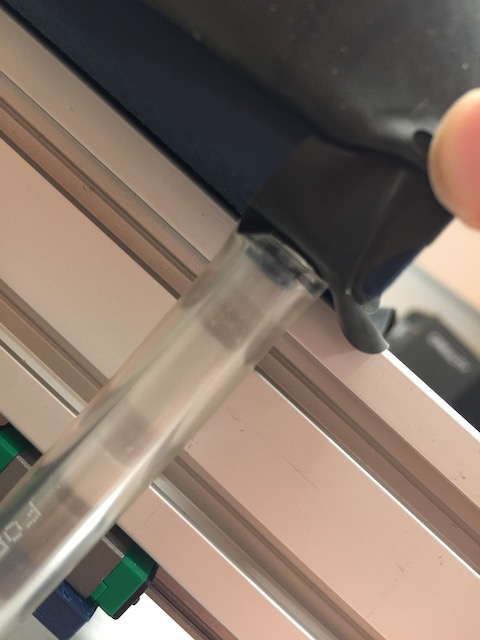
This is part of the coolant and abrasive slurry system. The idea here is to use a shop vac, which may just be the most widely accessible „compressor“ / „air pump“ to deliver coolant to the optics CNC I am building. My plan right now is to use the underpressure the stream of air exiting the shop vac generates to pull in a bit of coolant and cool the cutting process, without needing a separate water pump (in essence, the shop vac would act as the pump). Think of something similar to how a carburetor injects fuel into the fuel air mixture.
I started by pulling apart one of our shop vacs at night to see if I can find a way to manipulate the motor speed. A variable resistor might be the best way to control the motor speed. I have only rudimentarily tested its effectiveness in pulling distilled water from a channel in the side, but it seems like it could work. The only bigger challenge I came across is the fact that the water pulled in gets rather mistigfied into small droplets instead of forming a spreads stream. Next, I will make a board that can easily be interfaced via I2C to interact with the shop vac and change the coolant flow and extraction
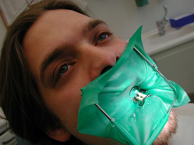
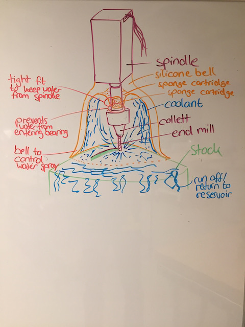
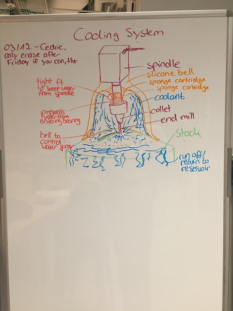
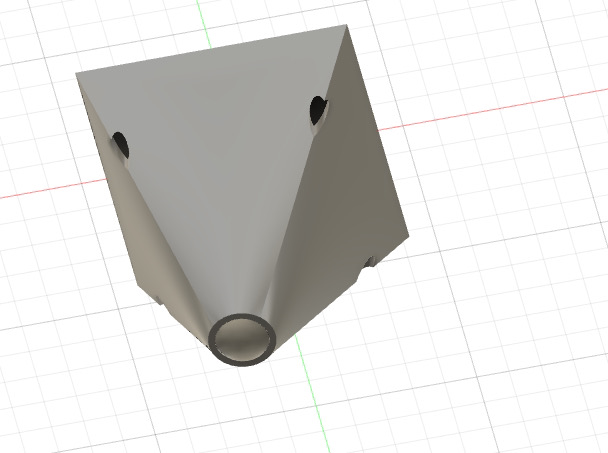
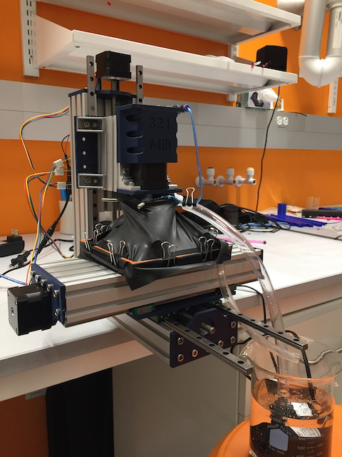
Kofferdamm Coolant Bell
This is again part of the coolant flooding and extraction system for the optics mill. I thought through different options of managing coolant, but ultimately, most options seem like they would be spraying coolant all over the machine, which is exactly the problem I want to avoid for a small machine like this. The current solution I am thinking about is a somewhat dentist-inspired approach. I am assuming it is not possible for me to locally extract all the coolant that will spray all over the part. Under that assumption, I want to contain the coolant as much as possible to one local area, have it spray all over the place in there but not leave that area in an uncontrolled manner. The best I could think of so far is a combination of a bell-housing that retains any spray water and contains it to a local area as best as possible. In addition, the top inside of the housing is designed to minimize water contact to the spindle. For the inside of the collet holder (?) and the spindle itself, I designed a sacrificial filter inspired by the ones serological pipettes use, that may have to be changed from time to time if it gets wet. I started making a mold for a silicone cast of this bell, in a screw-on fashion.

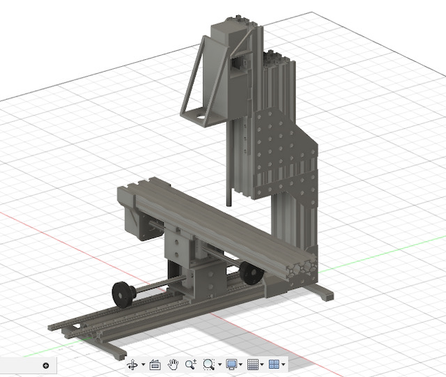
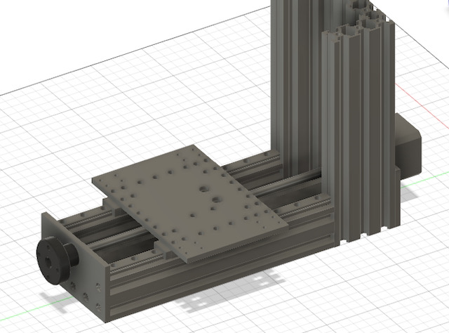
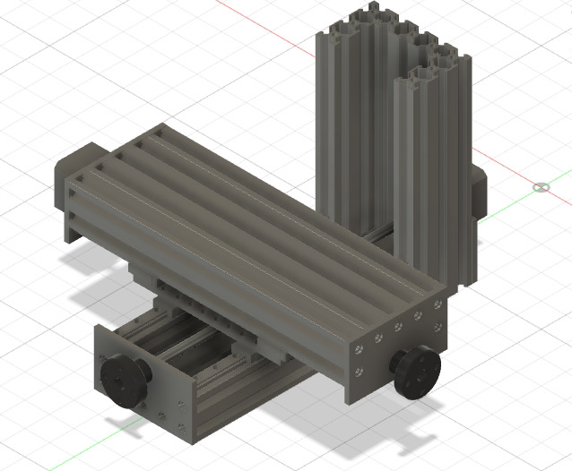
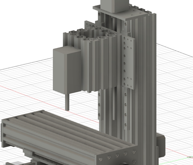
System: Optics CNC Mill
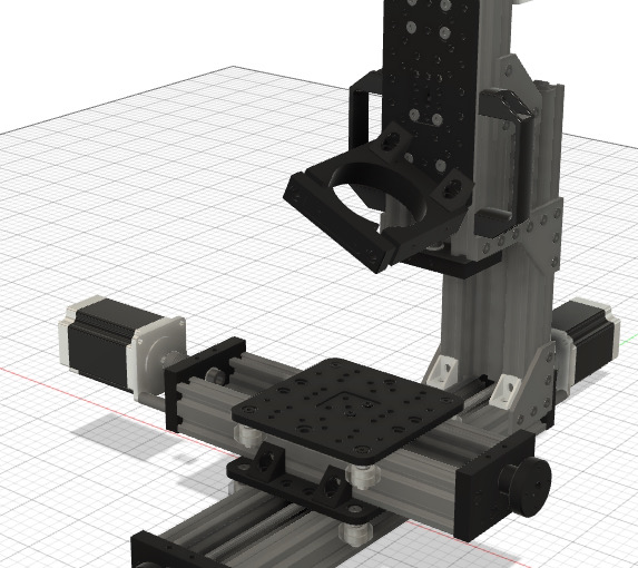
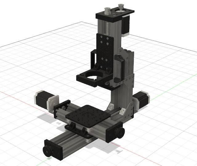
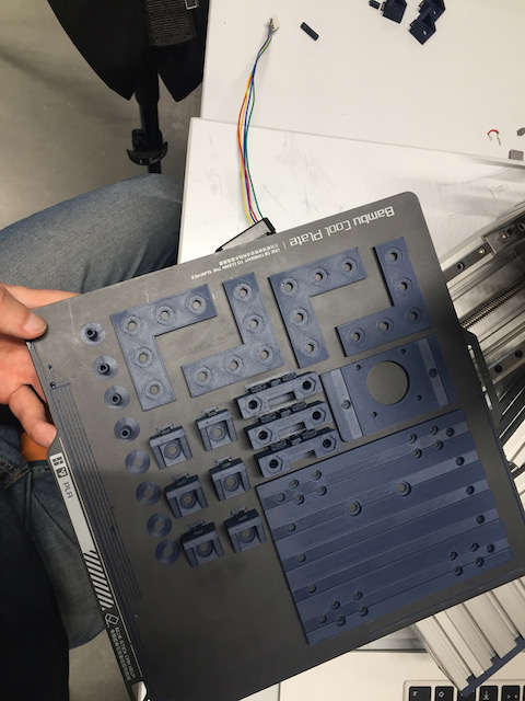
Most things happened here this week. I got components and parts from Jake and designed the mill as a 3 axis mill system, mostly going off of the design of the Open Builds Mini Mill and the Milo 1.5, but only using components CBA has readily stocked. Work in progress
TODO: Insert Fusion screenshots here...
Existing Projects for CNCs
Jake's Machine Week Machine Files Build Your CNC OpenBuilds Mini Mill Milo 1.5 PrintNC MPCNC04/22: Mill Update
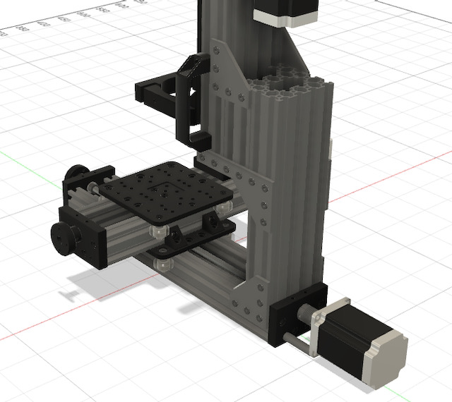
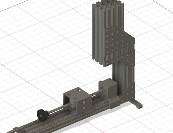
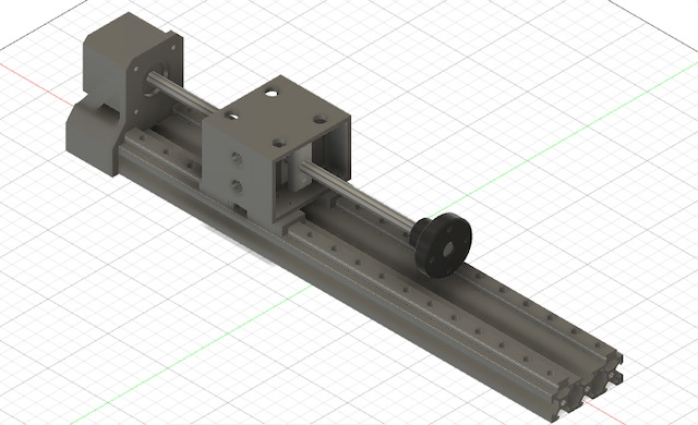
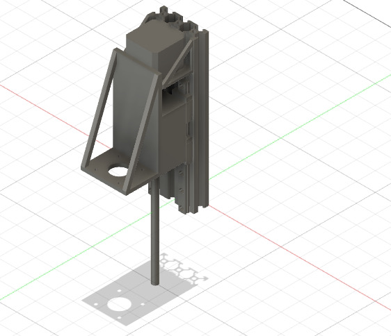
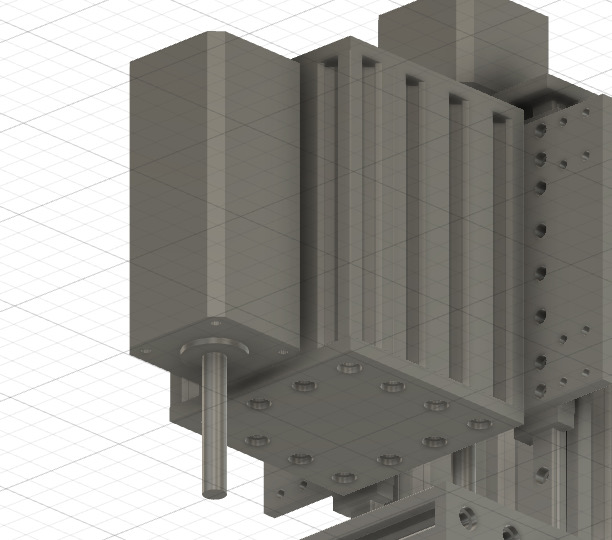
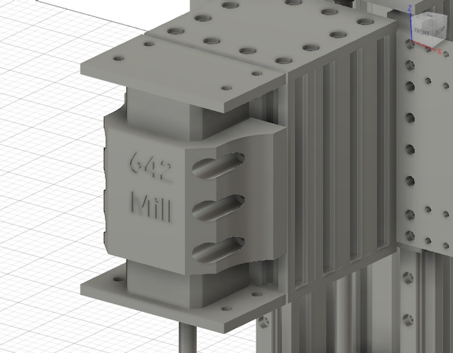
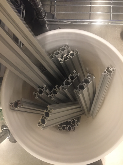
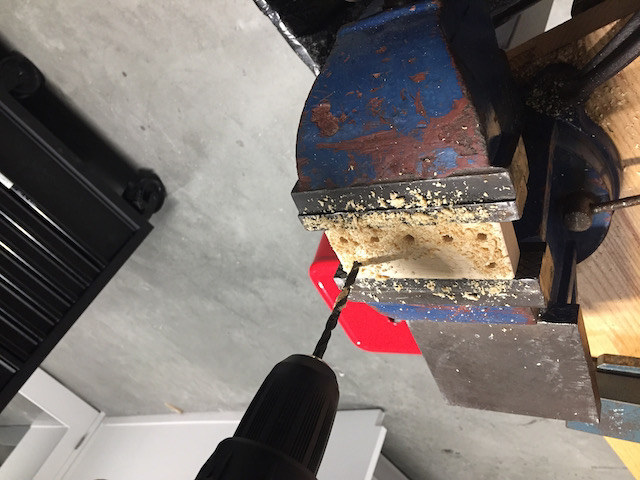
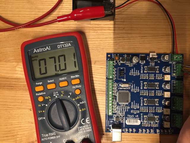
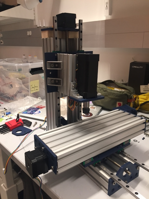
After fully designing the first version of my mini optics mill, I realized it is shit. Way too many thin-walled 3d printed parts. Way too wobbly on the z axis. Way too much play on the xy table. As this is the first time I am trying to build something with an accuracy of >1cm, this may come as a surprise to some of my readers. But I hadn’t anticipated it to be as bad. After coming to terms with the fact that my beautiful contraception will probably make nobody proud, I started all over again. This time, I designed the mill with a few key design principles in mind: 1. All structural parts of the frame should be from aluminum extrusions. No custom 3D printed parts here. I want the frame to be as rigid as possible, with the possibility of filling it with concrete later. The extrusions should be standard extrusions, nothing fancy that only one vendor carries 2. Anything supporting the xy plate and z axis that isn’t aluminum must be from something similarly sturdy. I did not want 3d printed parts here. So instead, I made sure that all the parts could be cut on a CNC, a waterjet or even just a band saw and a drill press 3. Only non-structural accessory holders, like clips for the tubing for the coolant system, can be 3d printed One thing that was important to me was to make a machine that could be reused by students in the future for any baby-mill based design. That required the use of just things we pretty much already have around the lab. With these principles, the new mill design is what I call the 3-2-1 Mill. It’s a 3-axis L-frame VMC, uses linear rails and ball screws on all axes. I’m using TinyG for the motor controls and a generic 24V power supply for my 3 Nema 17s. I need to do smaller loops!!
Later, when I picked up my components from Jake, he gave me yet another interesting
04/22: Coolant System Update
04/23: Modular Controller Update
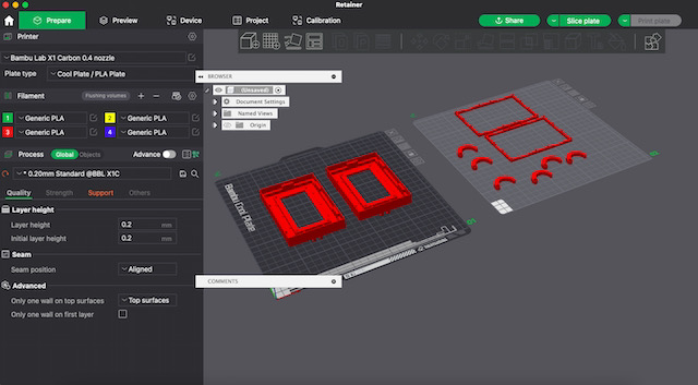
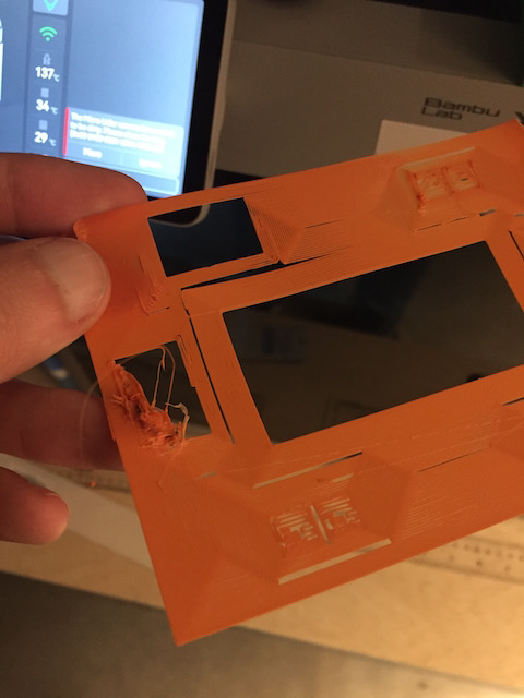
I finished the firmware for my controller, which is based on a controller Clark Teeple had built earlier. A set of commands can be used to control time points, but what’s maybe more interesting is the fact that trajectories can be sent to the controller. I‘m currently controlling it using a Python script. I also finished the PCB design for the controller and have milled it on the Roland.
.jpeg)

.jpeg)
.jpeg)
05/20: Demo Day
System: MTM 3 Axis Mini Mill
Process Summary
Version 1.0 of my mill: absolute garbage
Version 2.0: slowly getting there
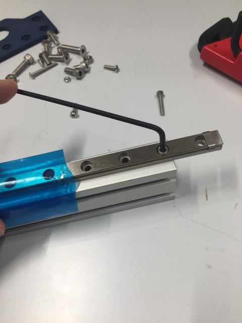
Alright, let's build the components
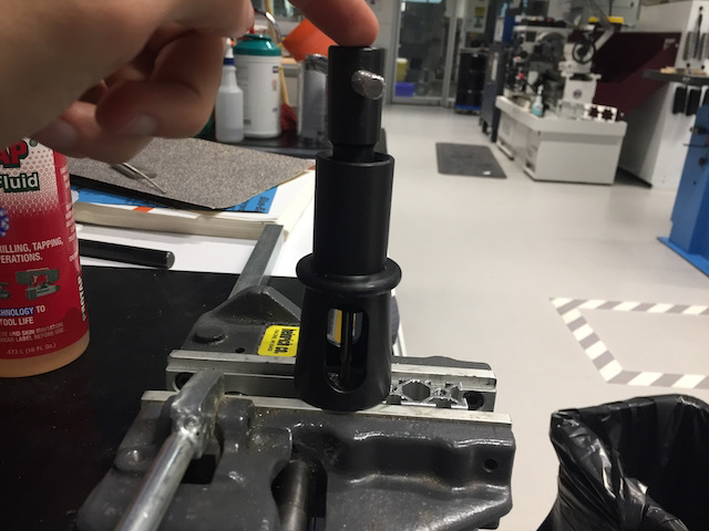
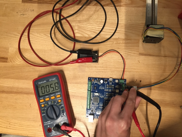
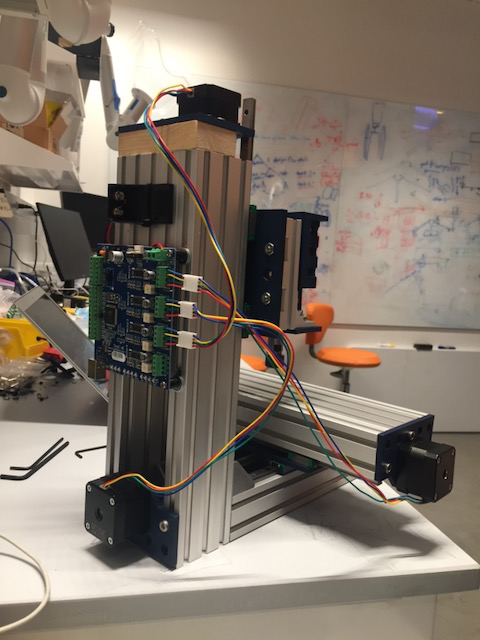
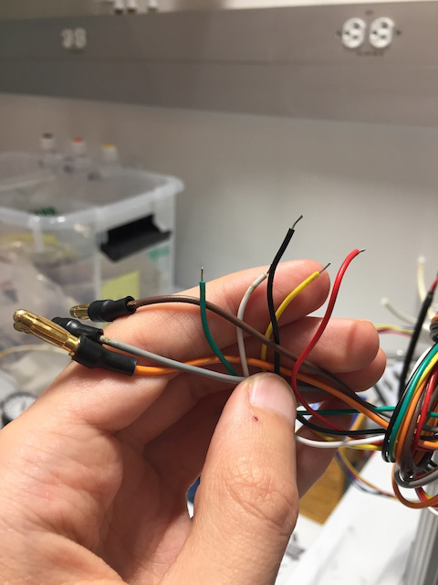
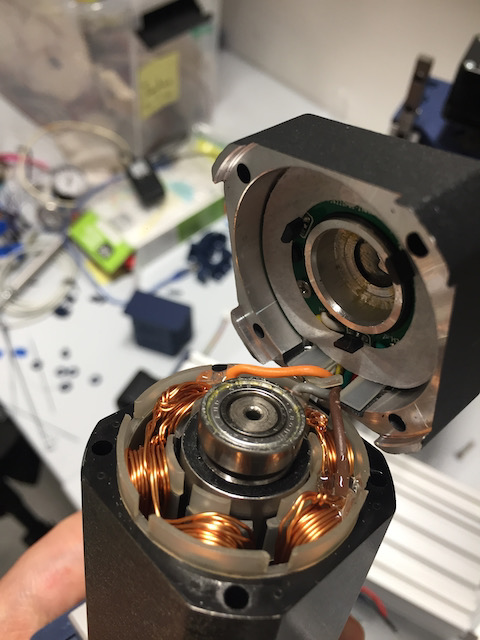
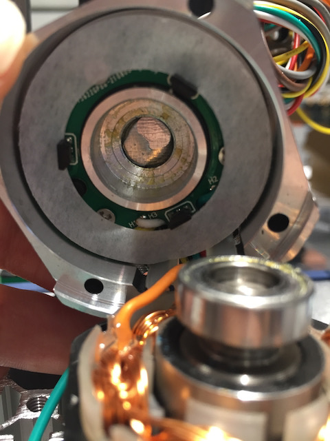
Getting the motors to run
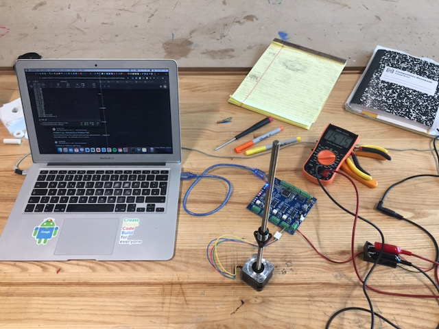
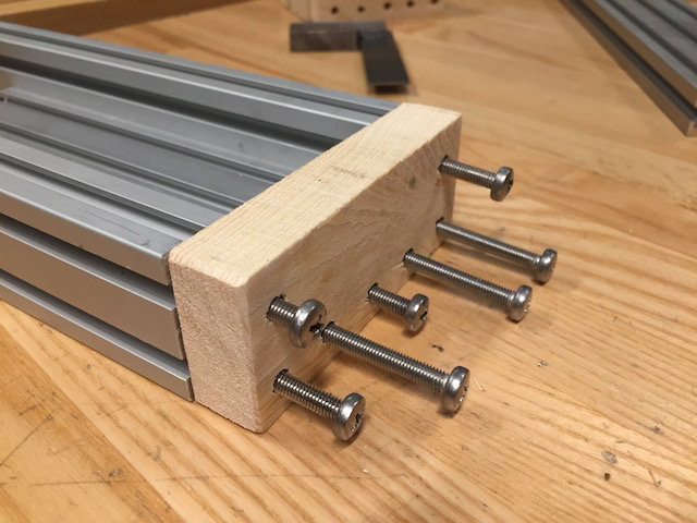
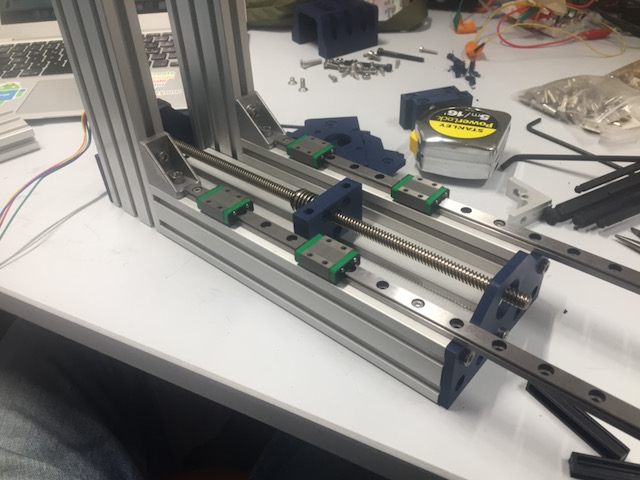
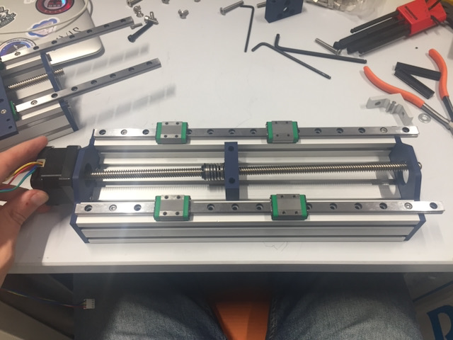
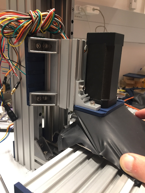
Putting it together
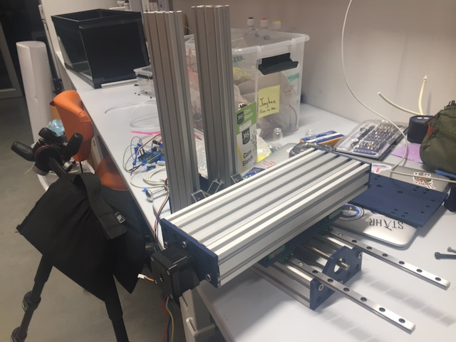
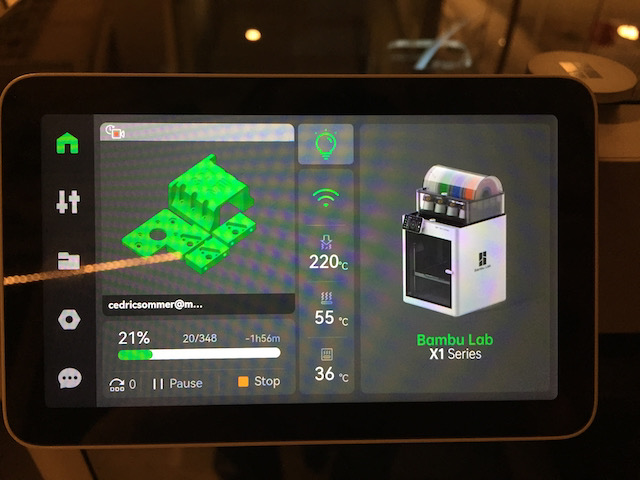
Running it
Actually running it - or at least trying to...
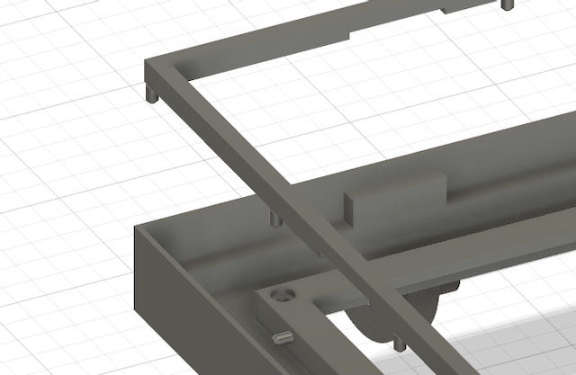
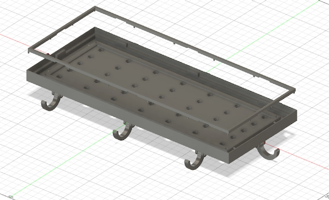
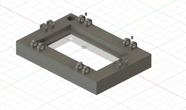
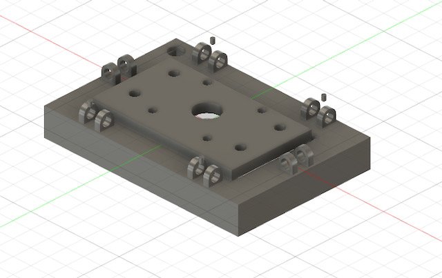
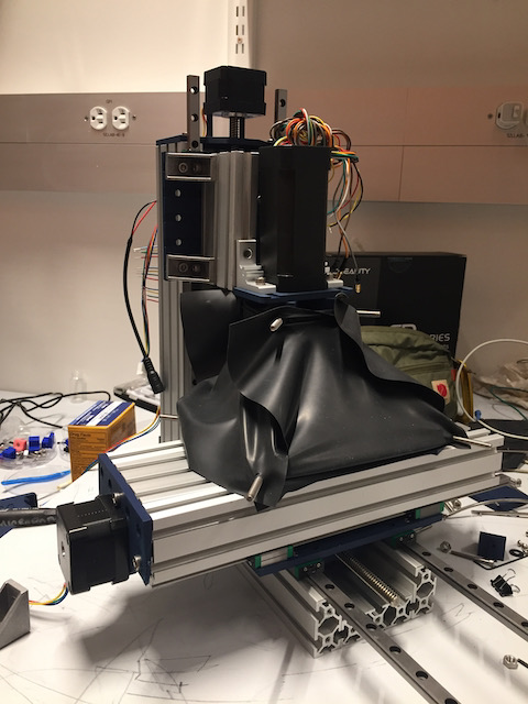
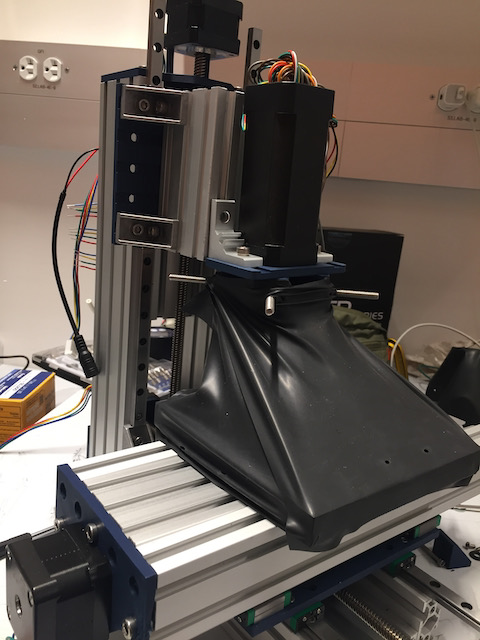
Component: NC Dam - Flexible Coolant Chamber / Tent
Process Summary
Drawing inspiration from dentistry
Version 1.0: a tent without poles
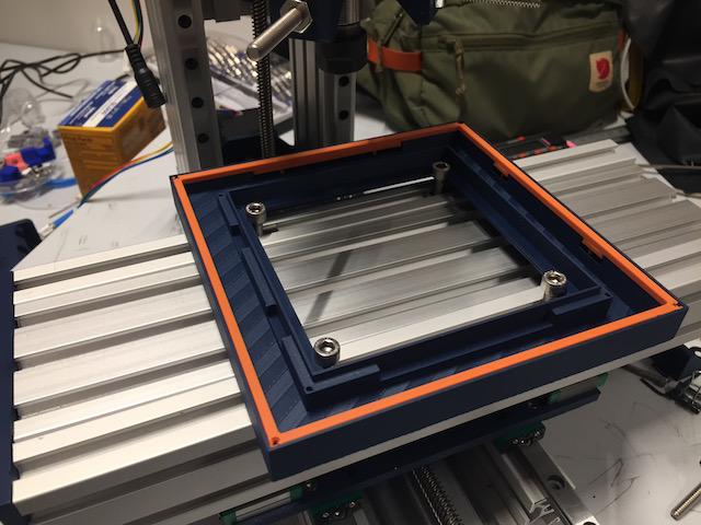
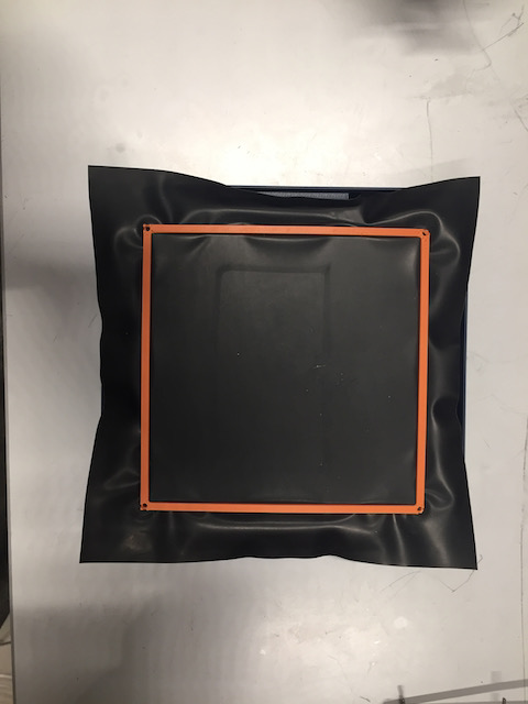
Version 2.0: including a rigid base and a runoff channel
Dry run
Wet run
Component: Pressure Controller Arduino Mega Shield
Process Summary
Design phase
Stuffing the PCB & testing
Fab Class Questions
What does it do?
> It mills, grinds, and polishes small parts. In particular, I hope to use it for custom optical elements
Who's done what beforehand?
> See Library of Machines above. The hobbyist market for optics is still dominated by pitch lapping machines. Optics CNCs are only available as high-end expensive machines. Some small mills are already out there, but I wanted to make one with as little 3d printed parts as possile and no proprietary parts to make a super cheap and sturdy mill
What did you design?
> A 3 axis benchtop-size mill with an optional coolant system
What materials and components were used?
See materials above, mostly TinyG as the motor controller, an ER11 spindle, and 3 stepper motors
Where did they come from?
> MTM repository, CBA stock
How much did they cost?
> Within a few hundred dollars
What parts and systems were made?
> See above
What processes were used?
> See above
What questions were answered?
> How a flexible coolant add-on system could be designed for hobbyists. Also, what a basic sturdy mill would be constructed like
What worked? What didn't?
> Especially for the coolant chamber, the dental dam can be finicky and constantly has to be under tension
What are the implications?
> High-end optics aren't just for the professional market. There is an opportunity to build a machine that allows hobbyists to create their own optics.
Blimp Update