Week 9

3D Biofabrication

Week 9: 3D Biofabrication

1. Design considerations for electrical stimulation systems

The stimulus waveform is approximately that of a square pulse of 5V amplitude. Describe what happens to the stimulus waveform with the bioreactor attached
When a bioreactor is attached to the circuit the amplitude of the voltage of the stimulus waveform is reduced.
Assuming there is a single impedance value for a single bioreactor can you think of an explanation for why the stimulus waveform might be distorted when connected to the load?
Impedance is the ratio of voltage to current (V/I). The current rating of your stimulation device is too low. In this case, a custom stimulator may need to be built
How might you expect the pink waveform to change if several of the same bioreactors were to be attached in parallel to this stimulator?
They would add more resistance so the value of the voltage would decrease even more
What recommendation for modifying the stimulator would you make to solve this problem?
They can create a custom stimulation system. According to the protocol the maximum current rating of the employed card is only 20 mA, so, given that the application would require a higher current rating, they could use an amplifier. In the paper, they suggested using the OPA-551 from Burr-Brown, chosen for its high current rating (200 mA), high voltage range (-12 V through +12 V) and stability in unity-gain configuration

Week 9: 3D Biofabrication

2.Morphological changes associated with electrical stimulation

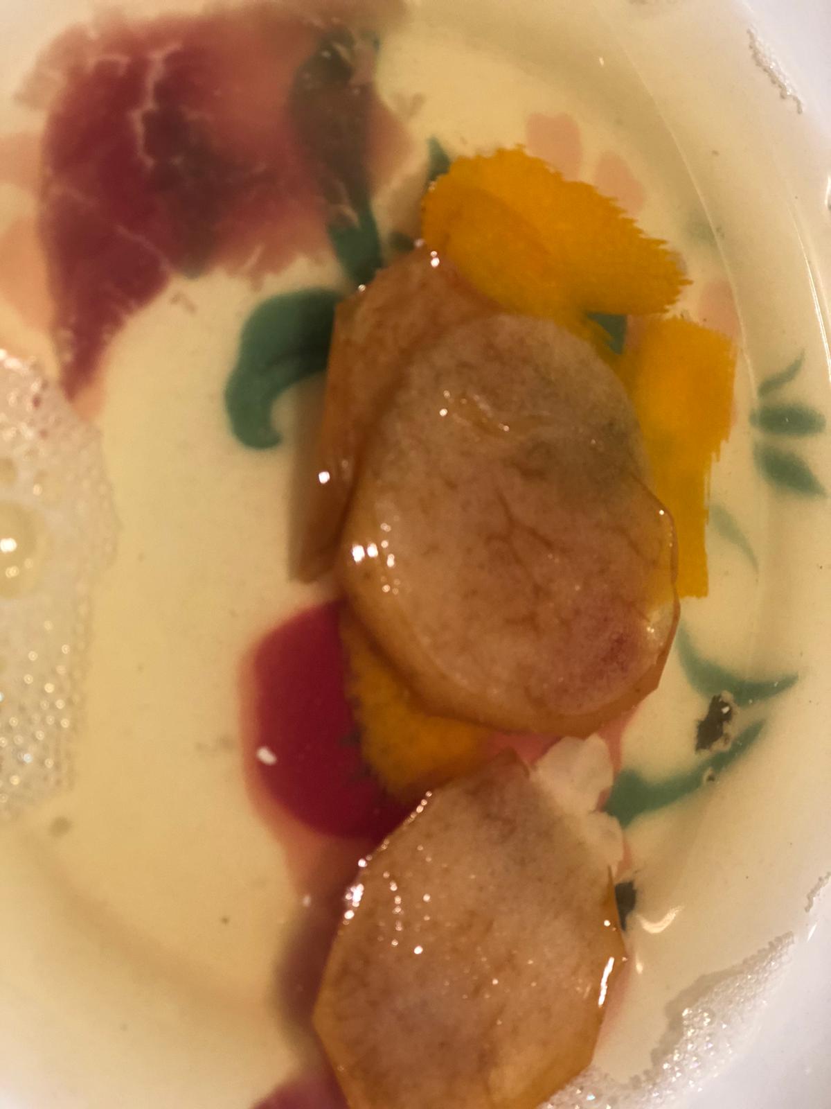
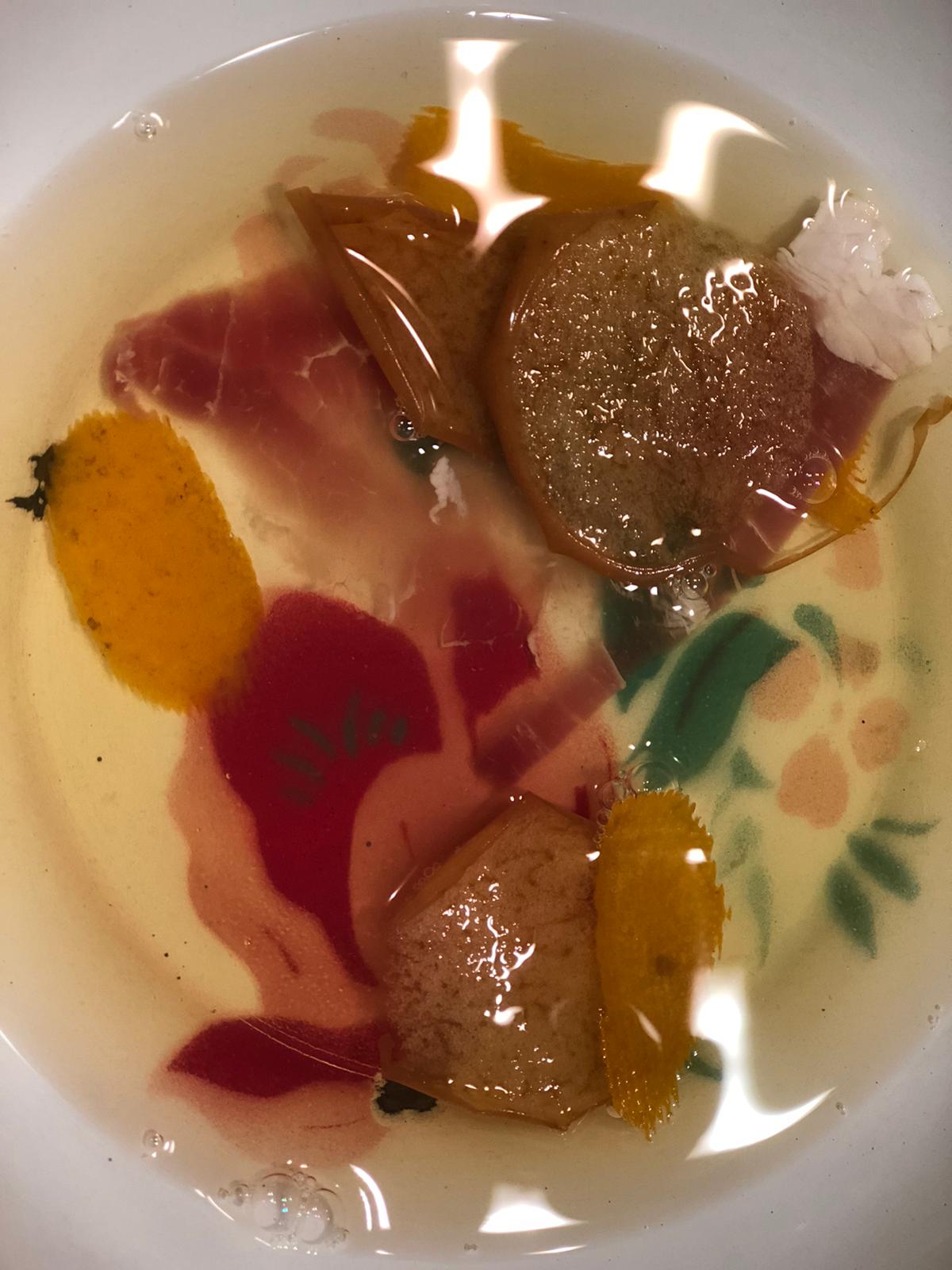
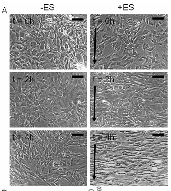
Using the above images, measure and graph (1) cell length and (2) orientation angle of cells at t=0, 2 and 4 h. Scale bar corresponds to 200 um and arrows delineate direction of the electric field. Describe the method used to identify cells (and include image captures at various stages of application of your method). State any limitations of your method, and suggest any potential improvements to the experimental setup.

I downloaded imageJ to do the analysis but could not find a way to improve contrast to identify cells. Therefore I decided to do it manually
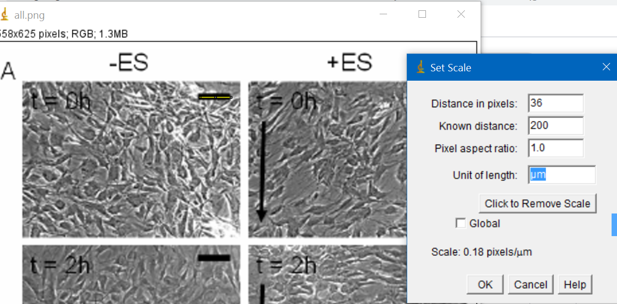
First I selected the scale and saw that it corresponded to 36 pixels

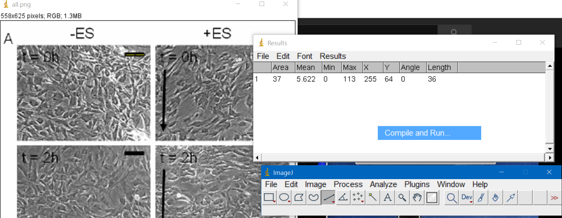
Then I went to Analyze --> set scale and adjusted it to 200um

Then I selected around 8-10 cells for each image and measure them myself, trying to capture the length of the major axis of the cell as they did in the paper

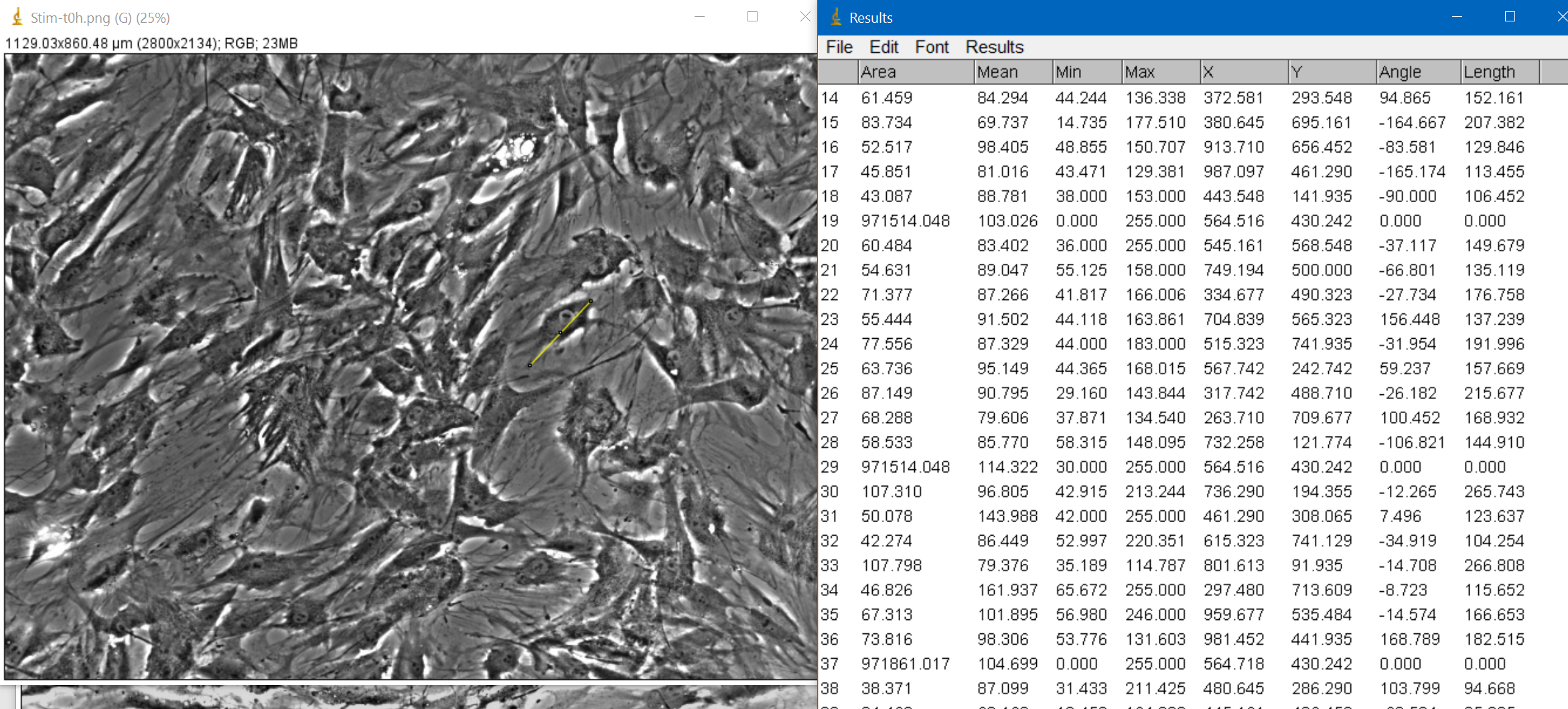
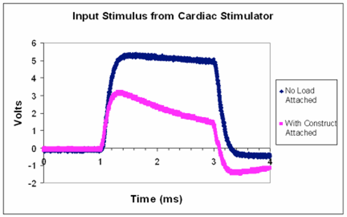
With that, I got the following mean results on cell length for each stage:

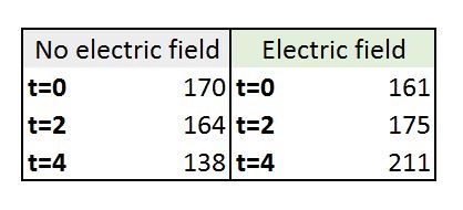
According to the paper, they were 159 at t=0 and 230 at t=4h.
Regarding the angles, the average of the results of my measures were not useful since they depended on the 8-10 cells I decided to measure. However, when looking at individual cells, I could see that angles were completely random at the beginning and tended to 0 at the onset of electrical stimulation since cells were aligning perpendicular to the direction of the electric field.

The method I used is limited since I drew the scale myself and measured the individual cells with the best of my ability. Improving constrast and using automatic measurement would definitely help to make sure that results are more consistent. I got similar results to the paper (in terms of the trend) but I would not be comfortable using my numbers since they depended a lot on the cells I decided to measure.
Given the role of mesenchymal stem cells in wound healing, state any conclusions you may draw from your above analysis. What other results would you like to see in order to support this conclusion?

Week 9: 3D Biofabrication

3.Design considerations for perfusion bioreactors

Paraphrase in plain English the worked example on pp 1191-93 in the Ratner Biomaterials chapter. State the assumptions and approximations regarding void volume, fluid velocity, channel geometry. How might you expect these parameters to change over time during bioreactor cultivation of stem cells towards bone tissue?
They exposed bone cultures to a force parallel to the cross-section of the bone (perpendicular to the longitudinal plane of the bone) to simulate physiological conditions.
Void volume: it is the “empty” space in a porous material, in this case they modelled it as 70% porous
Fluid velocity:
-Low shear stress: 0.0649 cm/s or 8.16x10^-4ml/s
-High shear stress: 6.49 cm/s or
Channel geometry: cylindrical (5 mm diameter and 5 mm long) with 109 channels per scaffold
I would expect void volume to decrease ad the bone tissue grows, fluid velocity to decrease to, while it encounters more resistance from the new bone tissue, requiring more fluid velocity.
Now, examine the below computational models of medium flow through anatomically precise TMJ bone constructs during bioreactor cultivation (refer to: Grayson et al 2009). (A) Color-coded velocity vectors indicate the magnitude and direction of flow through the entire construct based on experimentally measured parameters. (B) Construct is digitally sectioned, and the color-coded contours are used to indicate the magnitude of flow in the inner regions. What is the range of velocities experienced by the cells predicted by the model, using the equations from part (a). What issues might you expect with modeling this type of perfusion system during maturation of geometrically complicated bone tissue for 3 weeks?

Theoretical modeling of flow indicated a wide distribution in the magnitude (0–0.15 cm/s) and directions of flow velocities. The flow rates were highest in the inlet and outlet regions, adjacent to the needle ports. Because of the complex geometry of the scaffold, its flat base is not at the center of the chamber, resulting in spatial gradients of flow distribution across the base (lowest flow rates at far-right and far-left and near zero flow at the extremities) I would expect that with those differences in flow, cell density and viability would be affected but also, that we could benefit from it by actually being able to better direct the growth of the osteogenic tissue in complex bones. However the paper said that recent studies suggest that, with that range of velocities, cells maintained complete viability and exhibited characteristics of osteogenic differentiation


Week 9: 3D Biofabrication

4.DIY decellularized scaffolds!

I started my experiment on Saturday afternoon using what I had at home:
-Apple
-Prosciuto
-Orange peel