To play along at home, you will need the cad_ui application.
It is available as a bundled Mac application or as source. Note that the source archive includes the rest of the fab modules. These are wonderful tools but will not be covered in this limited tutorial.
If you're building
from source, the software uses cmake to automate the
build process. Details about dependancies are in the archive's INSTALL file.
Good luck!
.cad file?A .cad file is a specialized Python script used to define an object.
The only requirement is that the file defines the following variables
(all stored within a structure named cad):
cad.xmin, cad.xmax, cad.ymin, cad.ymax define the region of interest.cad.function defines the shape of the object.The following optional variables may also be defined:
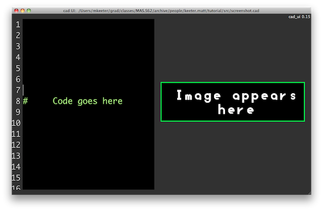
cad.zmin and cad.zmax define the region for three-dimensional objects.cad.mm_per_unit defines the number of mm per cad unit (default is 1)cad.type can be either "Boolean" or "RGB" (default is "Boolean")The cad_ui tool has a two-pane interface.
The file is written on the left, and its interpretation into an image appears on the right.
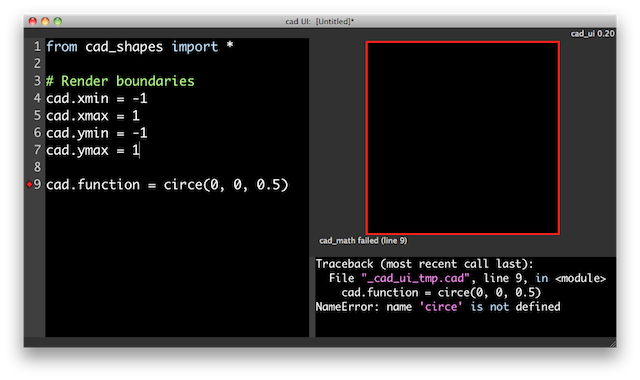
The border of the image indicates status, which is also printed below the image when trouble occurs.
To see more details on an error, enable "Show errors" option in the "View" menu. Below is a failed attempt to create a circle. Note that the line with the error is marked with a red arrow in the left margin.
The design tool comes with two libraries: cad_shapes and cad_text.
Let's use the circle function from cad_shapes to make a simple example:
|
 |
For reference, this is
what the example looks like in cad_ui.
The standard library includes add, subtract, intersect, and invert
operations. Let's cut a rectangle out of our previous example.
|
 |
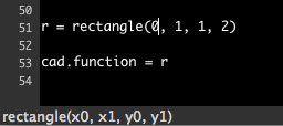
Note that if you start typing a function from the standard library, the GUI will give you a syntax hint in the botton left corner.
Because the .cad file is a Python script, it is easy to create complex
objects than lend themselves to programmatic expression. The example below
shows a cutout being rotated about the origin and repeatedly removed from
the base part.
|
 |
Below is an actual part designed as a .cad script. The part is a stand for
a brushless DC motor, used to keep it steady for benchtop testing.
|
 |
Now that we've covered the basics, the next tutorial goes behind the curtain to explain how objects are represented and manipulated.