
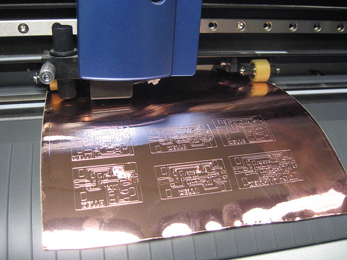
The circuits that you can cut on the Roland are limited by the width of the pen knife. As a rule of thumb, anything that you can cut with a lot of time and effort with an x-acto can be cut by the Roland, but if there are things that are too small for that they will probably also be too small for the vinyl cutter.
To use the cad.py software that goes with a lot of the FabLab machines, save your circuit as a .png. If you're using Eagle as your design software, you can output the layers that you want to use as a monochrome image, and use a 500 dpi to make sure you get enough resolution to contour the part. You can also use this design constraint file in Eagle to make sure your traces aren't too close together.
Use the .png as your input, and after clicking the cam button select .camm (for the roland) as your output.
For the vinylcutter you only need one contour, check all of the contour lines to make sure that none of your paths are being skipped. If the contouring is sticking two of your parts together, you can down the tool diameter to something untrue as a hack-- the tool really is 0.01, but changing it to for instance 0.005 will probably keep the integrity of your circuit even if all the parts might be a bit smaller than you called for. Similarly, if your circuit has a lot of spacing, you can make your circuit wider by pretending that the tool is wider than it really is.
You want enough force in your circuit to cut through the copper, but not through the backing. If you use too much force, the traces will also be dragged up with the cutting. I have found that setting the pen force to approximately 45 when the knife is sticking out about 1mm is pretty good, although this varies. While cutting the circuit and watching the vinyl cutter, you can dynamically adjust the pen force with the slider located on the right control panel of the machine. Adjusting the pen force to be lighter for smaller traces and heavier for larger ones tends to work pretty well.
It is necessary to maintain all of the relative positioning in the circuit itself. So the basic idea for making the circuit is to lift all of the cut copper out with pieces of masking tape, then to place them on your circuit substrate, and finally to weed out the excess copper. When putting on the masking tape, try not to press too hard as to set the pressure-set adhesive.
When you lift the circuit off, it is best to lift the circuit at a more obtuse angle to minimize the amount of traces accidentally left behind.

The circuits can be placed on any more or less heat-resistant surface. This can be glass, acrylic, wood or even cardboard or fabric. The surface will get hot when you solder on your components, but if you can solder quickly you can have some pretty sensitive surfaces as a base.
The 3M 1126 conductive adhesive tape is pressure-set, which means that it sticks once you press it. To make the circuits stick to your base, you need to push the copper all over as much as you can. I keep the masking tape on the circuit to protect it while rubbing all over it with the flat side of a pair of scissors or a ruler.

Then you will want to remove the protective masking tape, which you can do by peeling it off at as sharp an angle as possible, as not to rip up any of the traces. If the copper is lifting as you peel off the masking tape, push the masking tape back down and try to rub over the lifting area some more.

Now you need to tweeze all of the excess copper out of the circuit. Again, you want to peel the copper off at as sharp an angle as possible, so that you leave the rest of the copper that forms the circuit exactly in place. It is easiest to not try to keep the excess as one piece of copper, but to cut it away as often as possible.

Soldering is the same as soldering on any other PCB. However, while soldering you might find that some of your traces are looser than need be. Fix these by adding extra pressure to the trace.

to cut fine detail, try setting the force down to 10 but run your job from the same origin several times.
once the board is weeded and mounted on the acrylic, use the soldering iron on critical parts without solder as this will slightly melt the acrylic to make your traces more durable in these locations.
important! use plenty of hot glue around MTA connectors or they will rip up your traces when you unplug cables!
this tutorial was by nadya peek