
Automated Production Systems (APS) Gold-Place L40 Pick and Place Machine
An Illustrated User’s Guide to automating circuit board assembly with an APS L40
For access to the machine, email John DOT DiFrancesco AT cba DOT mit DOT edu
The L40 Pick and Place Machine helps with the assembly of circuit boards by automating the placement of small surface mount components onto boards, removing the tedious process of manually placing and soldering numerous small components.
→ Searchable PDF of the Official User's Manual for the APS L40 ←
The pick and place machine does exactly what the name implies, it (very accurately) picks up components and places them in the specified location. Solder paste is applied to the boards before they are placed in the machine. Once the machine has placed the components, the natural tackiness of the solder paste holds the components in place while the board is transferred to an oven. When the solder paste is melted, reflowed, and then cooled, permanent solder joints are created at each component, completing the population of the board’s surface mount components.
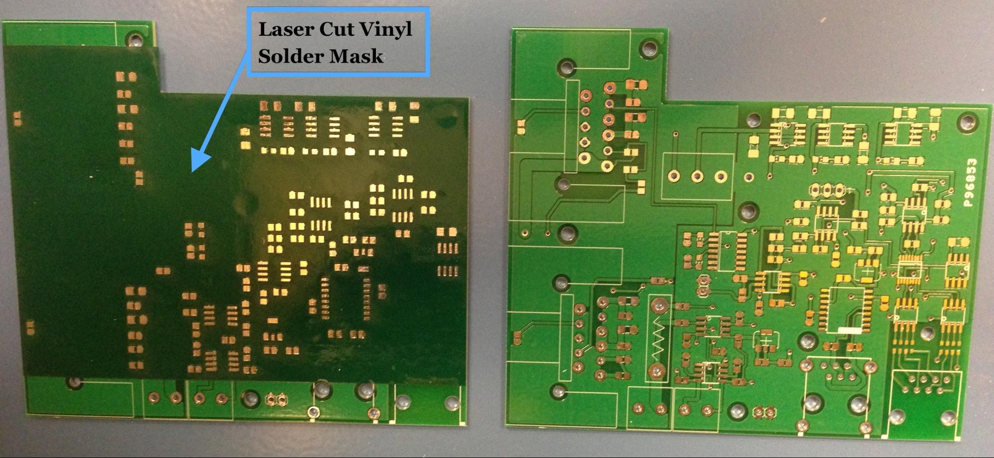
Solder paste must be applied to the solder pads of the board before operating the machine. We used a laser cut vinyl sticker as a mask with holes cut over the solder pads. Then, with the mask on the board, solder paste can be “squeegeed” onto the solder pads. Removing the mask reveals neatly solder pasted pads that allow the components to stay in place during Pick and Place operation. Although in some areas the squeegeed paste may appear to run the risk of bridging adjacent contacts, we found that in practice that the paste tends to reflow onto separate pads, with short circuits occurring very infrequently.
Safety: Because most solder paste contains lead, it’s a good idea to wash your hands after handling it.
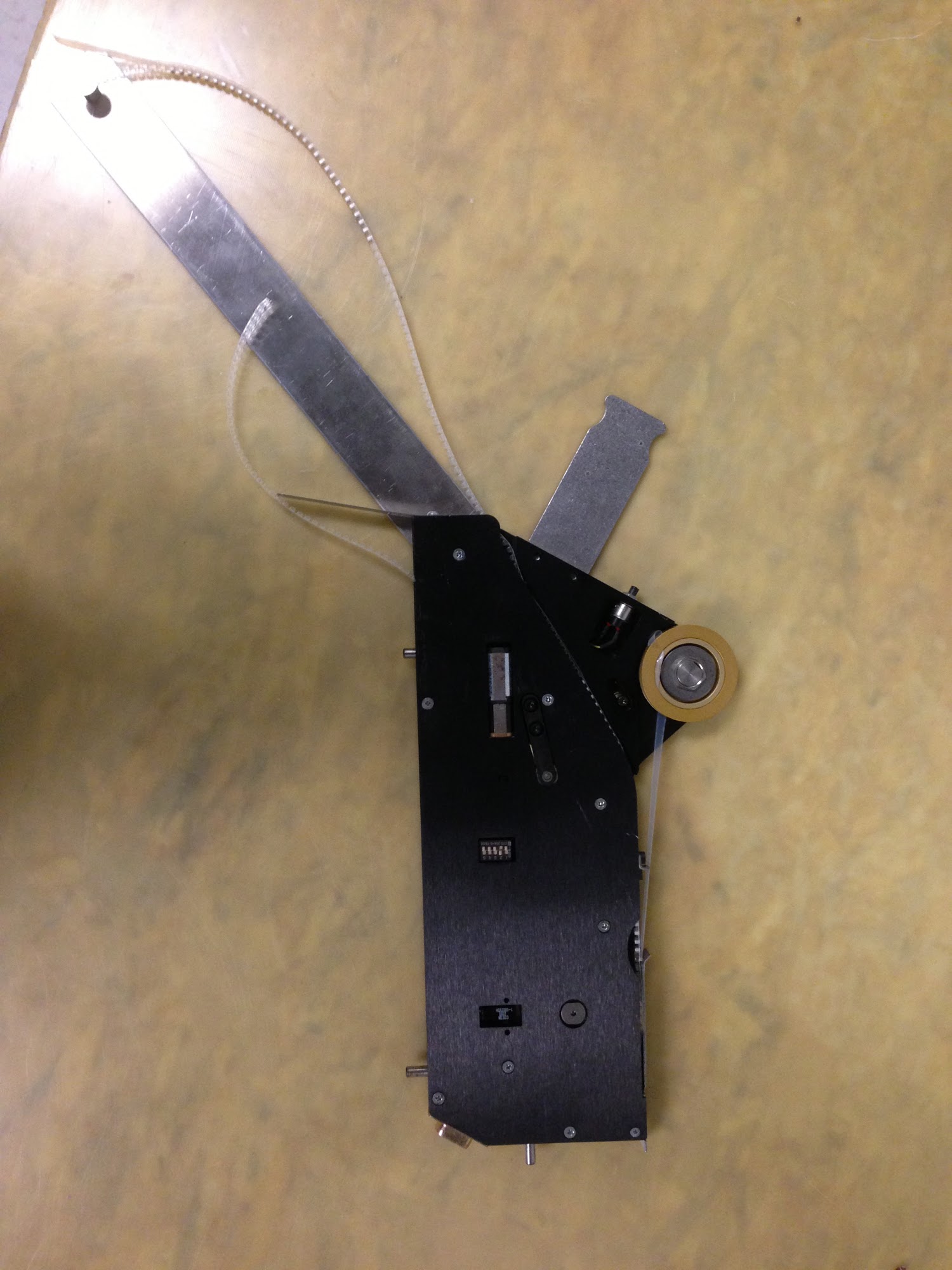
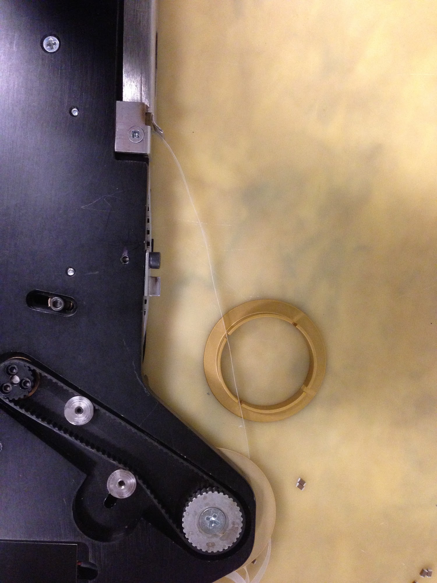
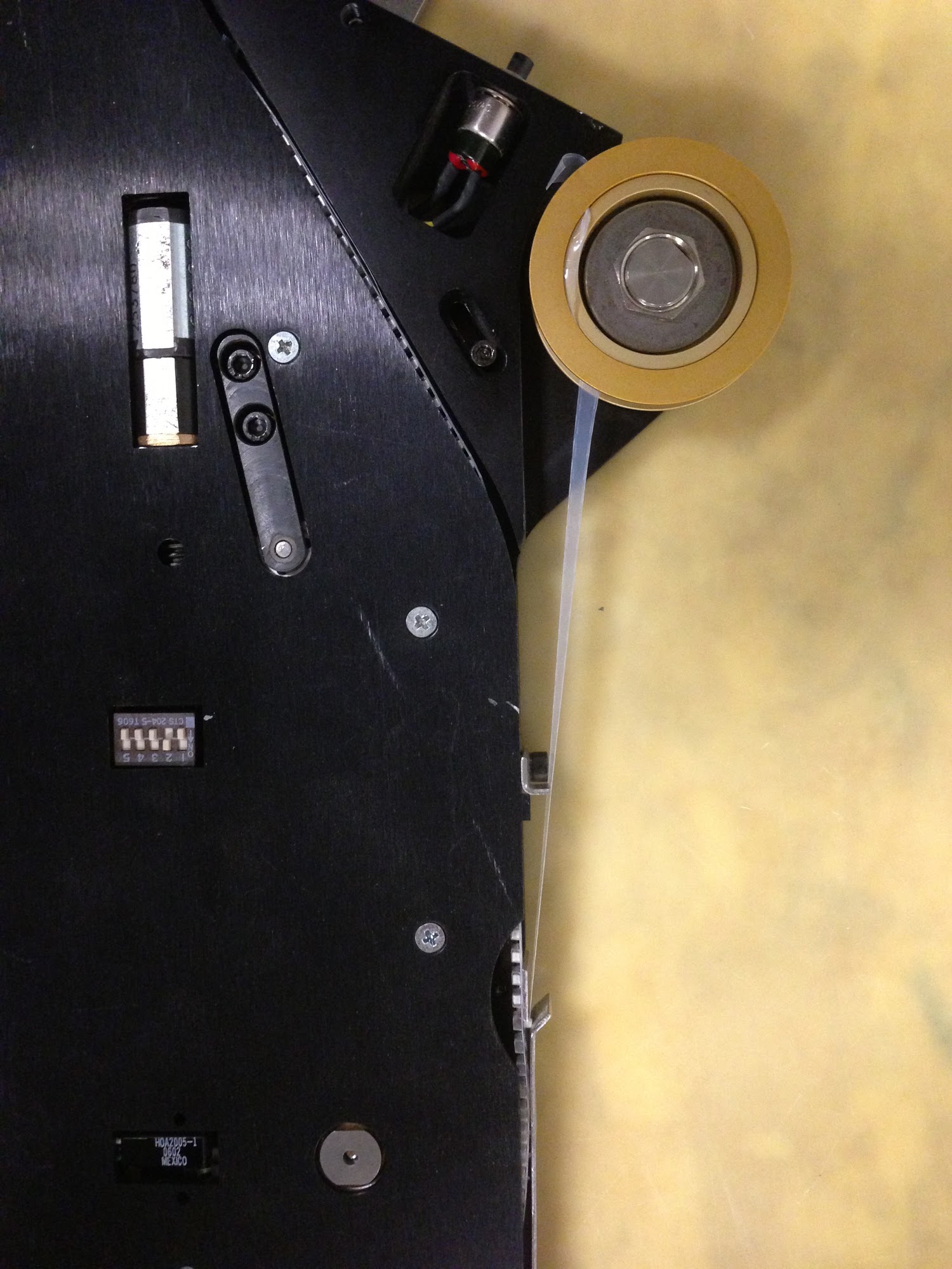
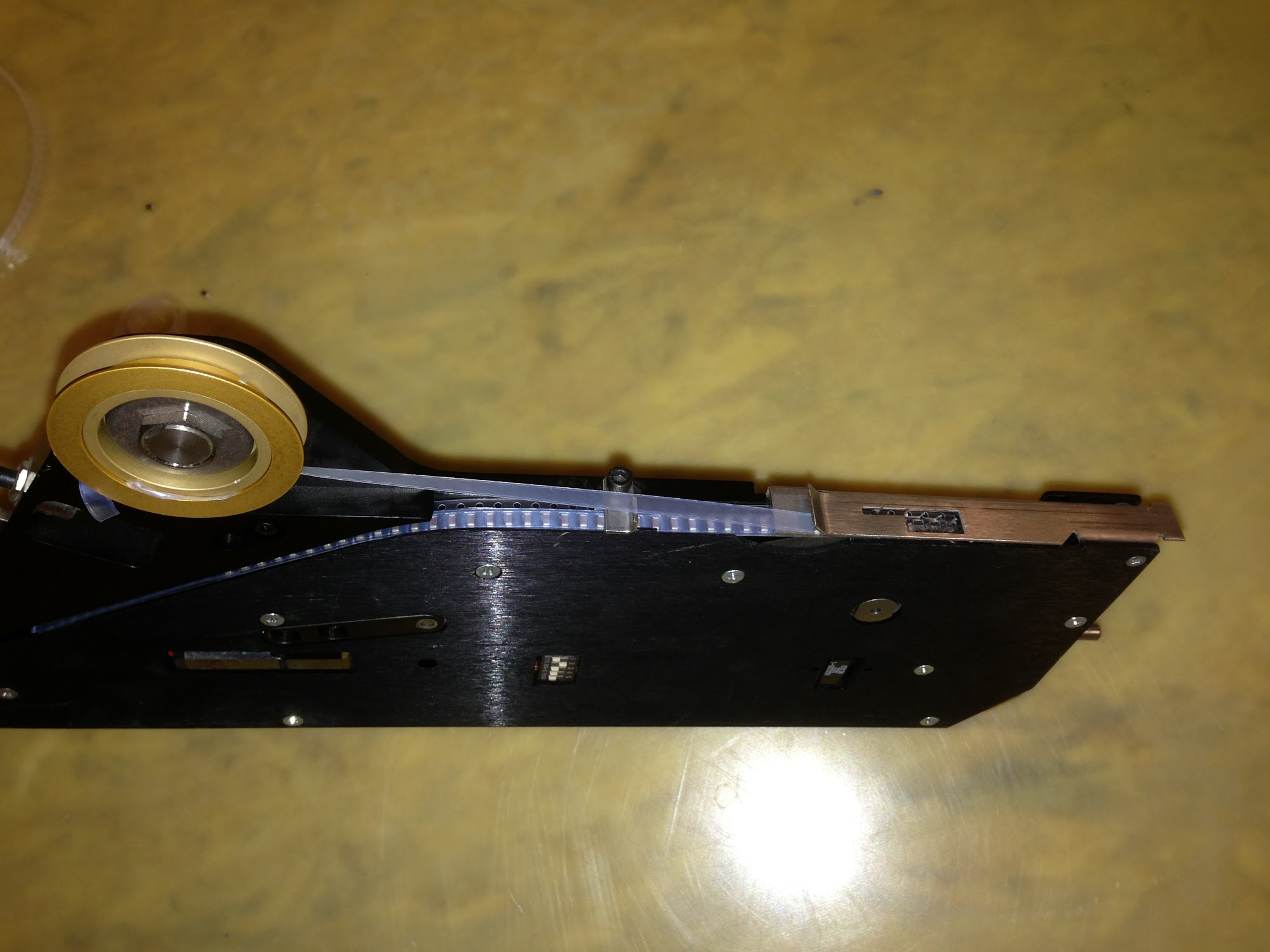
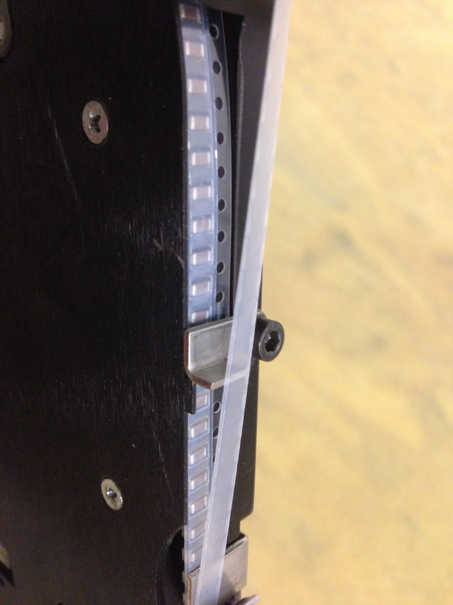
Use care in routing tape through the component feeders. Make sure the components advance properly by testing the feeder with the small button on the outside of the feeder after inserting it into the feeder tray on the pick and place machine.
It helps to buy component tapes/reels that come with extra tape length at the beginning so that you don’t waste a lot of parts in the process of routing the tape through the feeder. The tape won’t advance properly until the clear covering is pulled back and clamped into the gold-colored wheel, requiring 6-8 inches of “dead tape”.
Also, remember to write down which component you have put on each feeder!!!
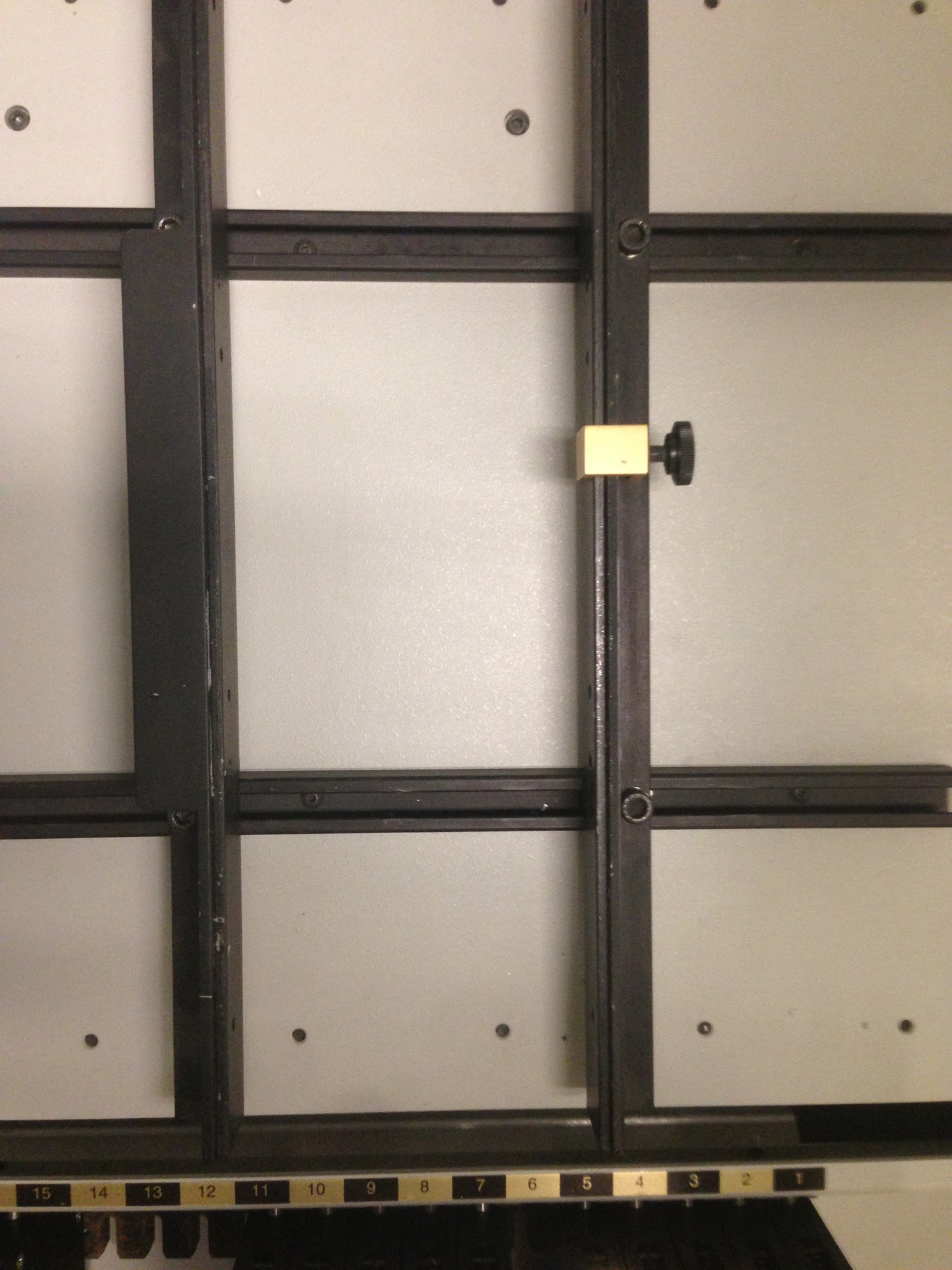
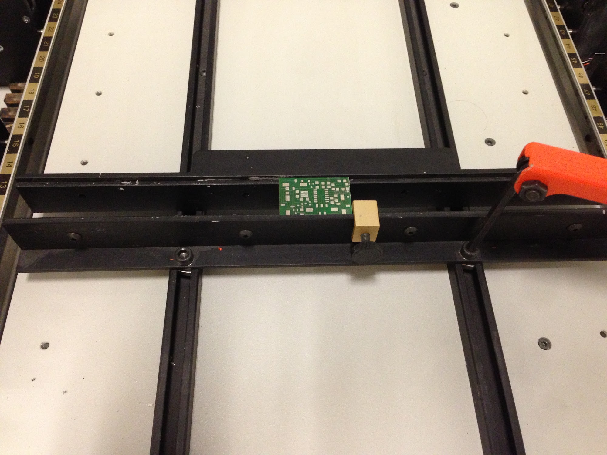
Using the guide rails, position the board on the machine and then lock down the placement of the board with the gold stopper. Make sure that the guide rails are perpendicular to the long rails running the length of the machine. If the guide rails are tilted, the board won’t line up with the pick and place machine’s X and Y axes, making proper component placement more difficult.
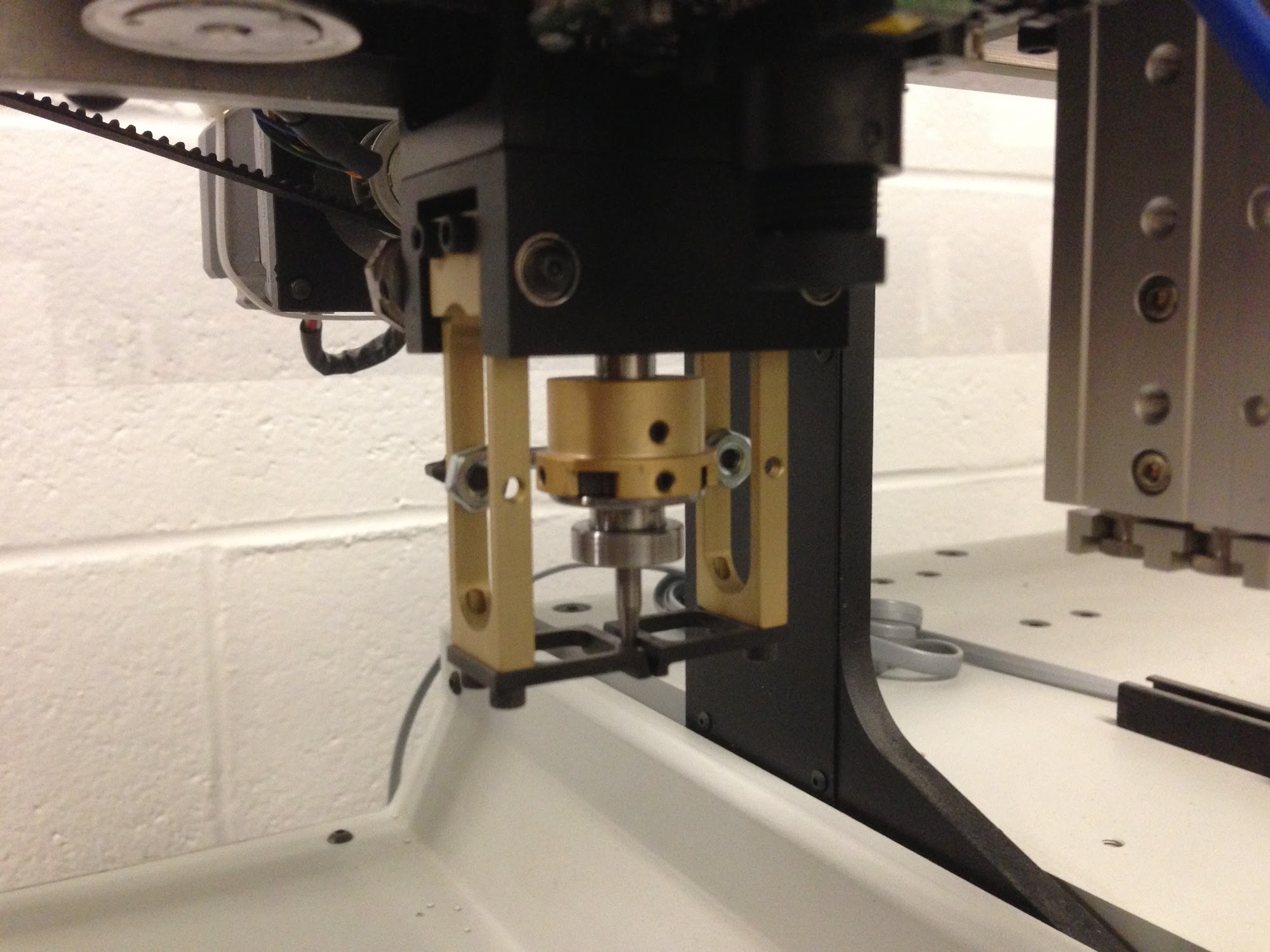
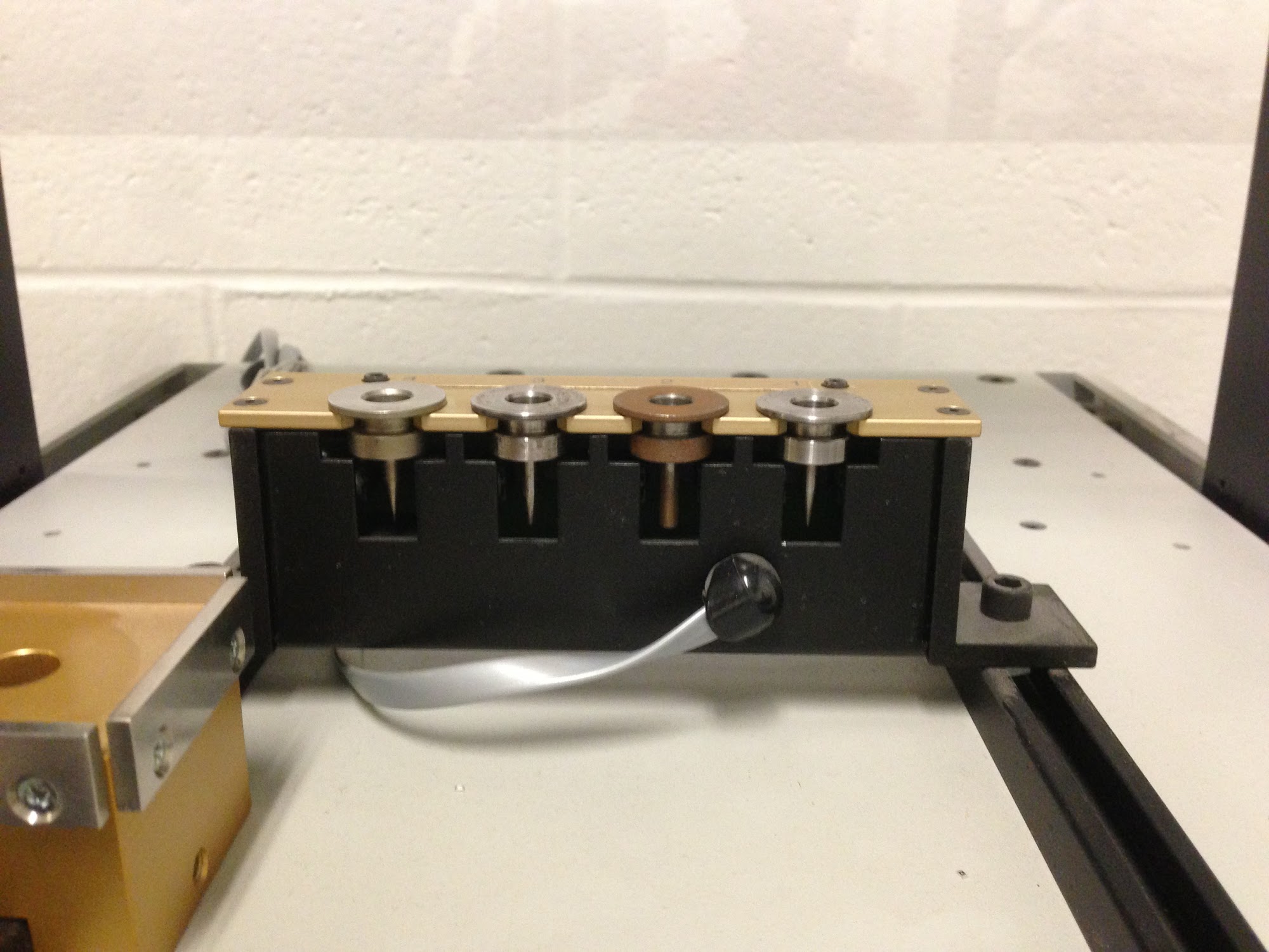
Pick and place vacuum head with tip (left) and tip holder.
Because of peculiarities with the Pick and Place software, upon startup the machine does not know which tip is attached (if any at all). This means that if there is a tip currently installed on the head of the machine, we need to manually remove it and place it in the holder. The software for the pick and place machine is incapable of attaching tools from holders other than the first so the preferred tool must be put there by hand.
Open the APS import software. You will need to come prepared with a text file specifying each component’s name, location, and rotation angle. An example are the .mnt and .mnb files generated by PCB software such as EAGLE.
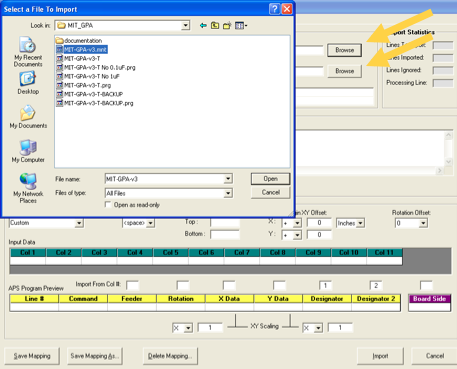
Choose your component data files (.mnt or a related format) and also pick an output directory. You will generate a .prg file for use in the pick and place control software.
Your file may not follow the standard Eagle format that the APS import tool knows how to interpret. In this case, you will need to create a “custom” mapping and tell the software what each column in your component file represents.
Use the “Ignore Lines” field to exclude headers at the top of the component file.
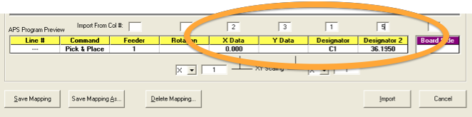
For custom mappings, enter the column number in the text file corresponding to the component X coordinate, Y coordinate, rotation angle, and designator label. Usually the feeder number is not included in the EAGLE text file; the feeder can be set manually once the component tapes have been loaded on the pick and place machine.
Check to see if the component coordinates are being read in properly. If there is an inches to mm conversion problem, you may need to use a scale factor of 25.4 or 1/25.4 in the “XY scaling” field.
When you are finished, choose “Import” and a .prg file will be generated in the chosen output directory. This file tells the pick and place where each component goes on your board.
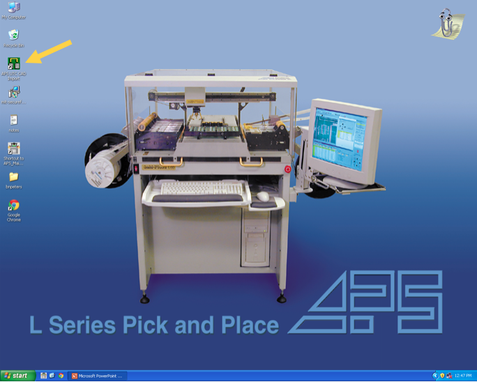
Now initialize the Pick and Place software. The first errors concern Homing and Login.
Select File > Log In. The username is “Admin” and the password is “Admin”. 
In the top right corner of the main window select “Reset” and then “Go Home”.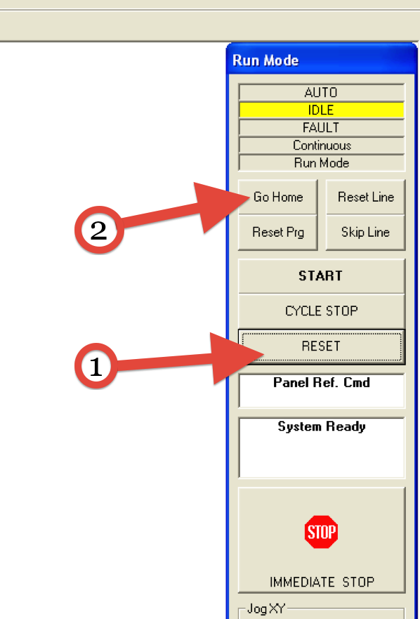
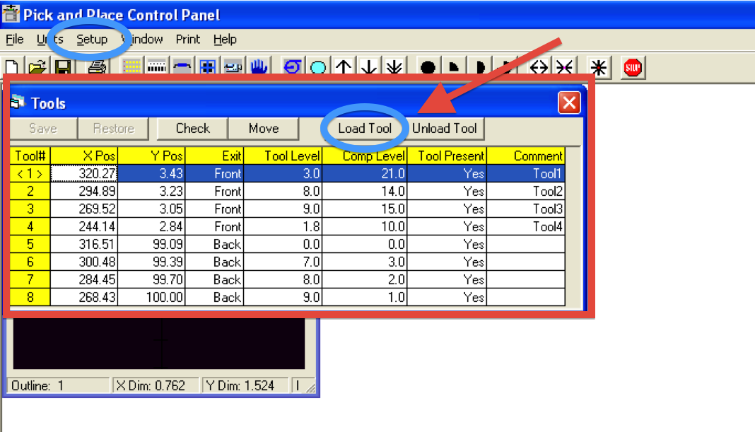
After the correct tip is in Holder #1, instruct the machine to attach the tip. This step is crucial to the use of the machine because it cannot place components without knowledge of the tool tip and the required vacuum pressures. See Common Errors and Troubleshooting for more information. Just a heads-up... when you click “Load Tool”, don’t be startled, the machine moves fast!
Under the File menu open your .prg file and verify that the component values display properly in the Pick & Place Program window. If the values are scaled improperly, go back to the APS Import software tool and play with the “XY Scaling” until the coordinates are correct.
When you are facing the front of the pick and place machine:
+X is to the right
+Y is forward
+Z is down
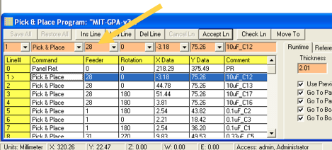
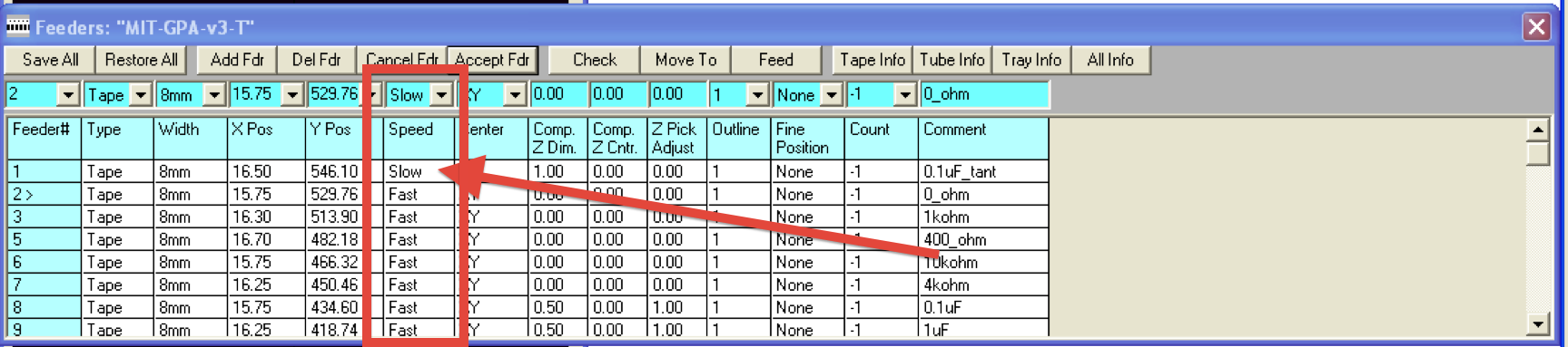
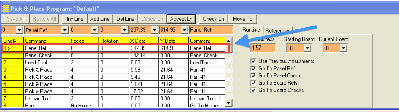
The software needs to know which feeder will be used for each component in the program. To set the feeder for each component, click on the relevant line of the program, type in the feeder number in the peach-colored field near the top of the window (see arrow), and click “Accept Ln”.
You can also modify the component positions as needed, bearing in mind that the positions are specified relative to the Panel Ref. on row 0.
Under the Setup > Feeder Address window, select the feeders in use and set their location as well as the component it contains.
Next, click the Feeders button on the graphical toolbar. Although the program does automatically generate the relative positions of the feeders, manual fine-tuning in the X-axis may be necessary for smaller components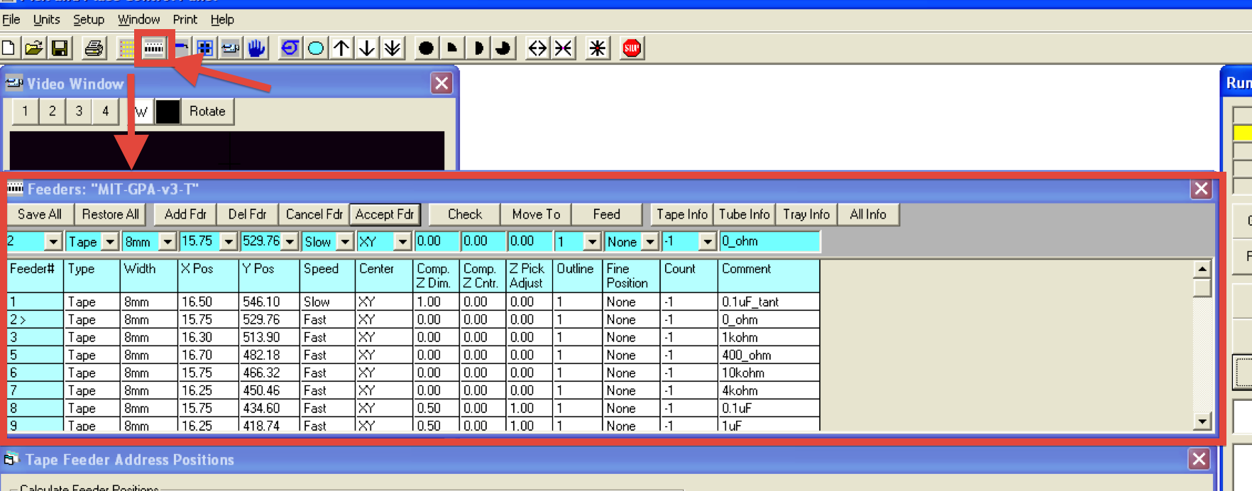
Verify that the tool tip lines up with the components in each feeder by highlighting the row of each feeder and then clicking on “Check”. The camera crosshairs in the Video window should line up with a component in the tape (choose Setup > Video if the camera view is not displayed). Slight feeder position adjustments may be needed from feeder to feeder depending on the exact position of each tape in the feeder.
You may also need to adjust the component Z dimension to accommodate differences in component height. For instance, 1206 footprint surface mount components will be taller than 0805 components by about a millimeter or so.
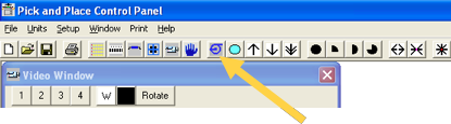
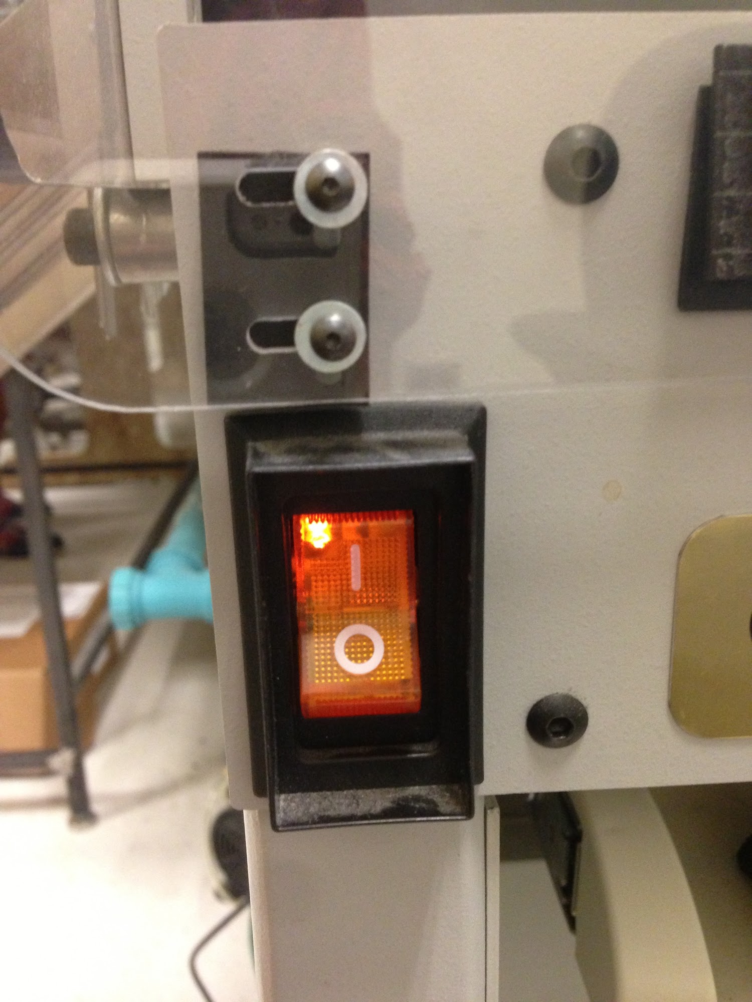
To test whether the tool tip can pick up the parts form the feeder properly, first turn on the vacuum using the vacuum button on the top toolbar (see arrow). Then choose Setup > Manual Controls to lower the tool tip (pick) and then raise the tip back up. Make sure the component is being held by the tip. You can try centering the component in X and Y, adjusting the Z dimension, and rotating the tool tip as needed. Then return the component to the tape, or for inexpensive parts, just discard the component and advance the feeder manually.
Click the Vacuum button again to turn off the vacuum when adjustments are completed.
To ensure that the import worked correctly and to set up the machine, define the local origin and align it with the (top left) corner of the board. Then try to manually or step-by-step go through a placement command to ensure proper execution.
To traverse long distances quickly, change the coordinates of a component or feeder (just remember the original coordinates) to a rough estimate of the location and move (Check) the head to that location. Then open the Manual Controls window and make subtle adjustments.
Open the hood and place the new squeegeed board in the correct spot. Close the hood. Make sure the current step is the Panel Reference Command. Then run the program, confirm the correct local origin and then start the placement operation. Once the placement is completed removed the completed board and align the next board.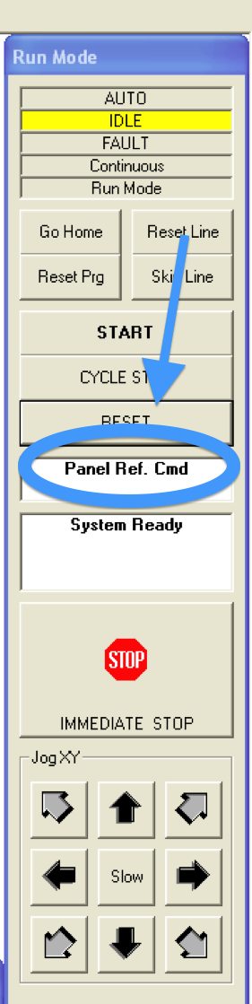
N.B. The component coordinates on rows 1, 2, 3, etc. of the program are relative to the origin panel ref on row 0. It pays to spot check these locations on the board by highlighting each row and using the “Check Ln” feature to make sure the camera crosshairs line up properly with the pad. Also make sure the component rotation angle is correct.
Often there are components that the Pick and Place is incapable of placing. These include larger components like IC’s, oddly shaped LED’s, or components not on reels. If the pads have been solder pasted, then it is best to quickly mount these components by hand with tweezers because solder paste does dry out after an hour or so.
After all the ingredients have been placed on the board. Reflow the solder paste by cooking it in a reflow oven (or just a non-food toaster oven). Typical bake time might be ~2 minutes at 475 degrees F.
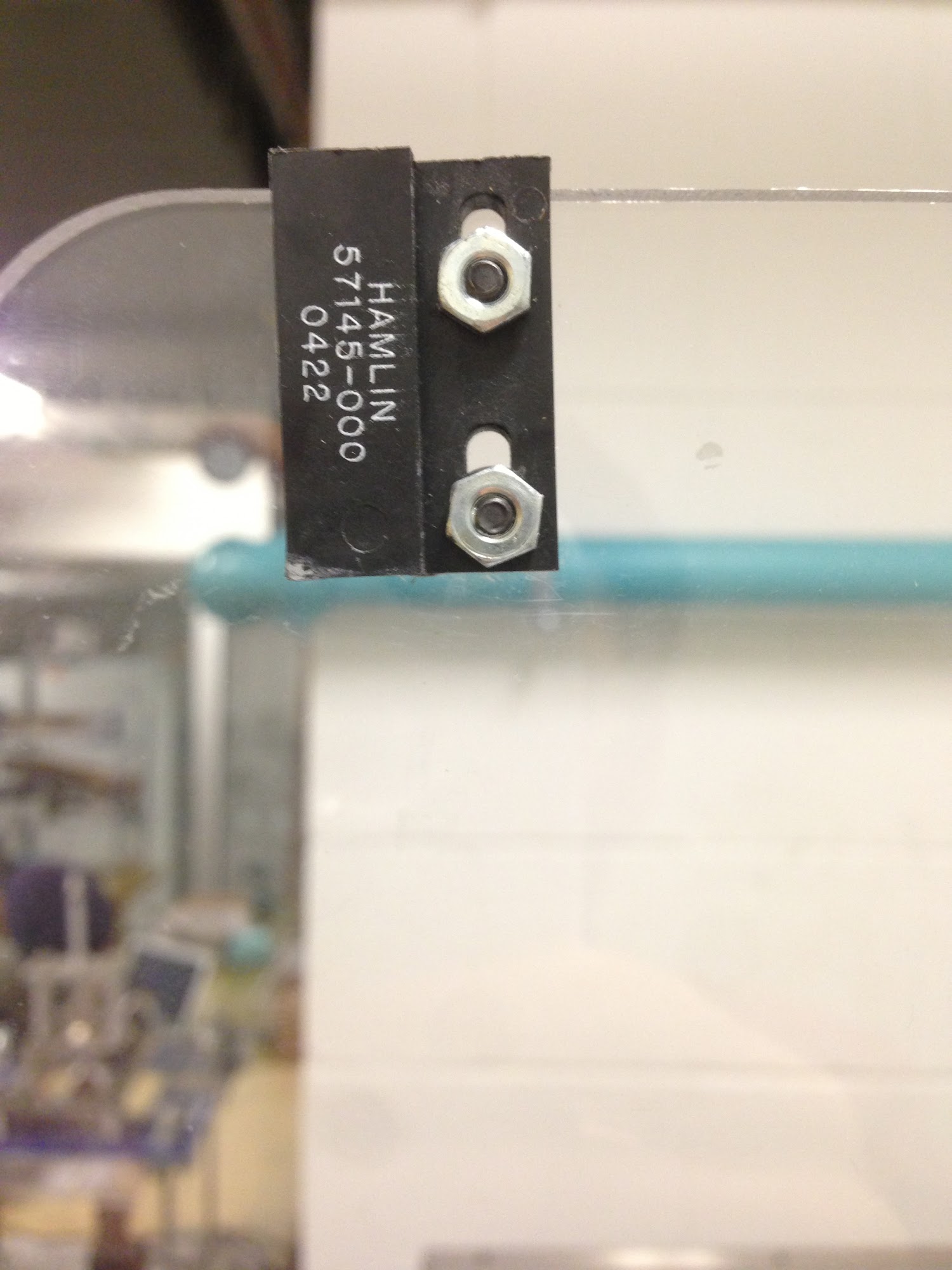
Either try re-aligning the permanent magnet mounted on the hood or find a strong magnet and install it on the bottom left side of the cover. At that corner there is a magnetic proximity sensor that senses whether or not the cover is closed. Because the sensor is fairly weak, without either an added or properly mounted magnet, it can be hard to detect a closed hood.
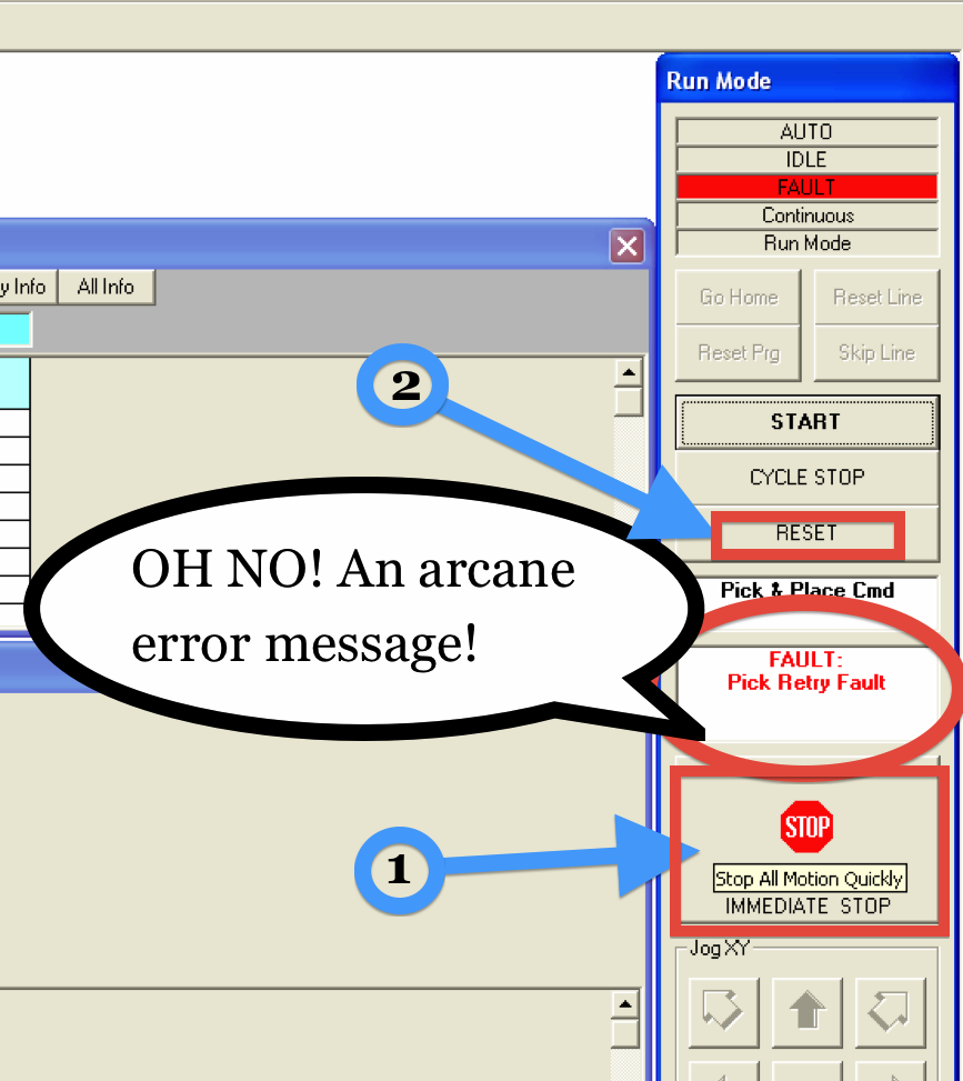
If there is a component on the tip when this occurs, drop the piece by manually moving the head to an empty spot and turning off the tool suction. This could be caused by either an inadequate vacuum pressure threshold or a misaligned piece not mating properly with the vacuum tip. Try to adjust the location of the feeder as well.
Otherwise it was just bad luck, manually advance the feeder either with the controls on the reel or with the feeder control on the computer and try again. For more laid-back (and potentially wasteful) operation, the Pick Retry attempts can be changed in the Parameters window so the Pick and Place machine makes more attempts after the first failure.
Pick up a component (manually or otherwise) with the tool. Then using the vacuum pressure reading from the Setup > Vacuum Status window change the thresholds under the Setup > Tool Changer window accordingly.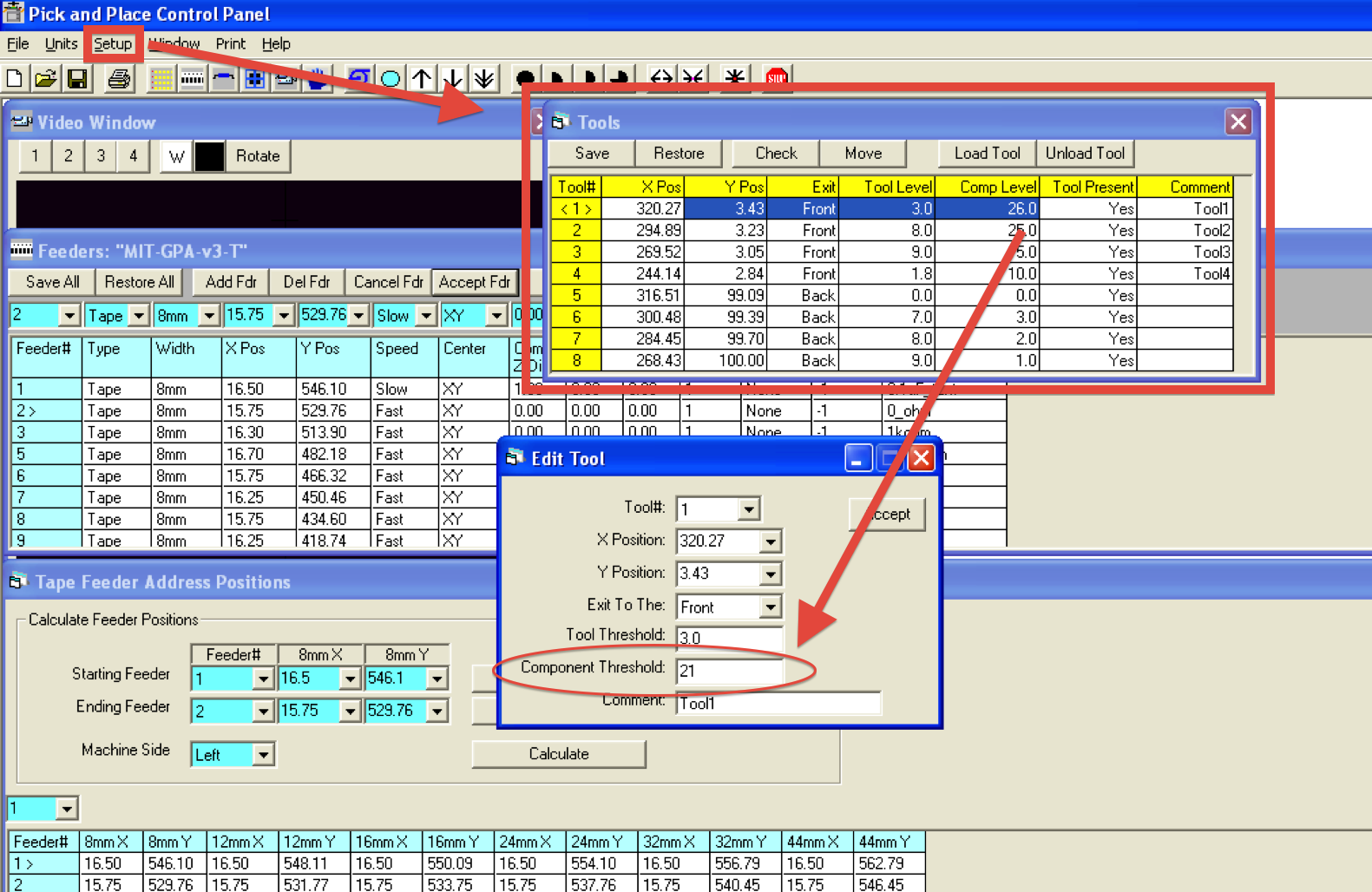
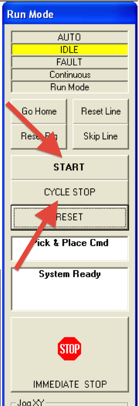
Normally, once the program in Running, it only stops after either an error or completion. This can be changed for more fine control or testing purposes. “Start” will run the program normally while “Cycle Stop” will go through one step (or “cycle”) and then stop to wait for commands.
The speed at which the vacuum head moves and places components is set under the Feeder Window and is independent for each feeder. Three speeds are available (Fast, Medium and Slow and can be changed under the Parameters window).