
You should be trained before you use this machine. Please email prashant.patil@cba.mit.edu for training information
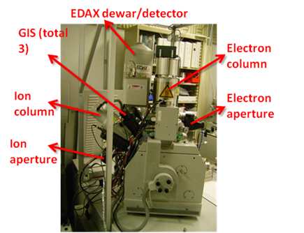
Machine name : Dual beam machine( Focused Ion Beam + Electron
Beam)
Model : FEI Strata DB-235 (S/N 020402)
Contact: Prashant Patil
prashant.patil@cba.mit.edu
617-758-9402
This machine involves two separated
beam columns. These irradiate energetic particle beams (Gallium
ion and electron). Primary function of these beams is imaging.
However, because ion has very high energy, it can easily etch
the target or decompose volatile chemicals by focusing ion beam
into certain area.
Detailed instructions and information
can be found in the manuals. The manuals are in the top shelf of
FIB room.
1. Normal emergency
- Turn off all beams
- Vent the machine
2. Critical emergency
Push red 'Emergency off' button
Note : This shuts down all machine parts, requiring days of
re-alignment and, possibly, lot's of service charge.
1. Turn off all beams.
2. Vent the chamber.
3. Load your sample.
4. Pump the chamber.
5. Turn on the beams.
6. Do your process.
7. Turn off all beams.
8. Vent the chamber.
9. Remove your sample.
10. Pump the chamber.
Before using the instrument, please sign the log sheet. Also please don't forget to report any error if observed at the end of the session.
When a button is ON, its Yellow and when OFF, its Gray
- E-beam Startup page: Turn off ‘HV’ button in
electron startup page (if not already turned off)
- Ion-beam Startup page: Turn off ‘HV' and 'Source' button in ion startup page (if not already turned off)
- Patterning Startup page : Click ‘Control’
button in 'Gas Injection' and check if heat 'Off' button and Needle
'Out' button is yellow. If not turn them on.
- Go to 'Detector' menu and select 'OM' from drop-down list
- Turn on Light and observe the sample holder in TV.
- Open nitrogen cylinder (~40psi)
- Open the purging valve located
behind the emergency off button.(Careful! Do not push EMO
button by accident.)
- Click ‘Vent Chamber’ button either in electron startup page or
ion startup page.
- Click ‘OK’ at the confirmation dialog box.
- Wait ~3min and see the chamber sealing whether there is gap,
meaning venting finished.
- Open the chamber, close the purging valve and nitrogen cylender
- Place proper stub and carbon tape
on it.
- Attach your sample.
- Place height standard beside the stub.
- Raise the Z height to 5mm point by Z dial.(Note : Pay special
attention when your sample is not planar, or too large. Above
5mm point, it may touch or break machine parts.)
- Use the height standard. The top notch is 5mm point.
- While looking in to the TV slowly close the chamber and make sure that sample don't collide with the electron beam column.
- Press the chamber handle with one hand and click ‘Pump’ button in
electron startup page
- Let go the chamber handle when the sound of pump become quiter.
- Click on OK on the window that appear on computer.
The sample holde will recenter itself wrt to electron beam column
(observe that in TV)
- In the menu, go to ‘Stage-Edit height map’, press ‘add’
button, then press ‘close’.
- Select the 'SED' detector from 'Detector' menu and turn-off the light
- Wait until chamber pressure drops below 1.3e-4 mbar showing
‘Vacuum status : Vac OK’. (However, for FIB CVD, pressure must
go to e-6 level.)
- The time varies depending how long you opened the chamber. The
longer you open, the more water molecule adsorbed on the
stainless steel chamber, resulting longer pumping time and
poorer vacuum level.
- E-beam Imaging
1) Filament is always on. So
you only have to click ‘HV’ in electron startup page. Check
bottom ‘E-column HV’ shows preset accelerating voltage.(You can
change acceleration voltage.)
2) Click ‘Primary beam – E’ button
3) Set your desired acceleration voltage in electron startup
page. You may choose proper spot size.(Default : 3) Click ‘SRH’
button in buttons collection.
4) Click ‘Starts/freezes scan’ button.
5) Change contrast and brightness in the electron startup page
or MUI. Also, magnification.
6) Move your stage by the joystick. You can also double click
the image using mouse to make it center.
7) Optimize your image by focus and stigmator control in
MUI.(Unless you go very high resolution, you don’t have to much
worry about staigmator. Focusing control would be enough in most
cases.)
8) High quality image can be obtained by clicking ‘Grab 1E’
button in buttons collection. To save image, select File – Save
– Image in the menu. Default image save path is ‘SharedDocs on
‘192.168.1.2’’.
- Ion-beam Imaging
a. Click ‘Source’ in ion startup page.
b. Check the bottom status window. ‘Emission Current’ must be
stabilized at 2.2uA.
(If it stays zero, go to NOTE below.)
If a
warning sign appears which says "Source has started but could not
achieve emission preset value" click on 'Apply' button on Emission
current tab.
c. Once current reaches stable value, click ‘HV’ button. Check
bottom ‘Column HV’ shows 30kV.(Ion acceleration voltage is
fixed.)
NOTE : Gallium is low-temperature melting metal. So, once it is melted, the supercooled phase is maintained for a couple of days. However, finally, it will be solidified again. In this case, the extracted current would drop to below preset value(2.2uA). Then, we need to re-melt Gallium with high current. However, this high current evaporates significant amount of Gallium source, causing reduced lifetime. Therefore, heating must be conducted in very restricted manner.
To operate heating function, first set the current to 2.9~3.0 A in ‘V/I slope’ box of ion startup page. Then, click ‘heat’ button once. The heating will be conducted for 1 minute. Please take a careful look at ‘emission current’ gauge in ‘status’ box. Once the reading goes high indicating ‘++’, heating is successful. If this does not work, wait about 1 minute, and repeat heating again. Typically, the emission starts within 2~3 times of heating.
Once emission starts, FIB automatically controls extractor and suppressor voltage to adjust the current to 2.2 uA. However, sometimes the control does not work well. In such a case, you must adjust the voltage levels manually. Fix extractor voltage to 12 kV, and change suppressor voltage. Make the emission current close to 2.2 uA. Fine tuning will be conducted automatically once ‘maintain preset’ in ‘emission current’ box is checked.
Even though you re-activate the ion source, the V/I response is unstable initially. Wait about 15~30 minutes to stabilize the current emission.
2) Click ‘Primary beam – I’ button
3) In I-beam menu, set your desired aperture. First, try imaging with 1pA (1pA have very poor imaging
capacity) if you can't image then select 10pA (it is most
widely used and pragmatic minimum) If you increase the aperture size, physical etching
would be very active. Be careful.
4) Click ‘Starts/freezes scan’ button.
5) Change contrast and brightness in the electron startup page
or MUI. Also, magnification.
6) Move your stage by the joystick. You can also double click
the image using mouse to make it center.
7) If you find it difficult to locate your sample you can also use the optical microscope inside the chamber. First, go
to detector menu and select 'OM' then turn on the light. You can zoom
In/Out using the controller in fron of the TV. Position your sample
just below the e-beam column using the joystick.
8) When done position your sample, turn-off the light and select 'SED' again. Never turn on the light when detector other than 'OM' is selected.This could damage other detectors
7) Optimize your image by focus control in
MUI
8) High quality image can be obtained by clicking ‘Grab 1I’
button in buttons collection. To save image, select File – Save
– Image in the menu. Default image save path is ‘SharedDocs on
‘192.168.1.2’’.
- Ion beam etching
1) Activate the image with low
magnification and move to the working area. Keep the searching
time short to minimize damages during searching.
2) Magnify the image to your desired magnification, and blank
the beam.
3) Draw your pattern using drawing tools.
4) Select your pattern using selection tool(arrow button). Then,
go to work page. Check ‘Serial’ instead of ‘Parallel’. Choose
material file(etching : si.mtr) or input your own beam
conditions like dwell time, overlap and process time. Change the
thickness by inputting the number in Z box of pattern definition
tab. Also, you can change the pattern dimension by putting the
numbers in the X and Y boxes.
5) Click Start/Stop Patterning button.
- Material Deposition
1) Bring the sample at eucentric point
Eucentric point is the point where electron beam axis, ion beam column axis and stage tilt axis intersects. In principle, all the work should be done exactly at this height. However, since beams have focusing tolerance, it is not very critical during imaging. But, in case of deposition, needle should be inserted, and this insertion is optimized at this eucentric height. If your sample is not in the eucentric height, the needle may hit your substrate causing physical damage.
1) Make sure that e-beam FWD is 5mm.
2) Position you sample just below e-beam and make sure that it doesn't
collide with e-beam column when the stage is tilted to 52 degree.
3)
4) In the work page, input 52 degree in the ‘tilt stage’ tab.
5) Using Z dial, change the height to make your feature centered
again.
6) Click ‘Add’ button to update your modified height.
b. Material deposition using GIS(Gas Injection System) handing
1) Go to work page, and click
‘Control’ button in gas injection tab. (GIS1:Platinum,
GIS2:SiO2, GIS3:Copper.)
2) Heat the source in advance. At least 10-15minutes are
recommended. Be careful not to click ‘Zero’ button.
3) Once the temperature reaches, status indicator shows red
color.
4) Activate the image with lowest magnification and move to the
dummy area. Then, insert needle by clicking needle ‘In’ button.
If you can see the needle hits your substrate, click needle
‘Out’ and lower the Z height(~100um), then update new height.
Repeat until no collision occurs.
5) Draw your pattern using drawing tools.
6) Select your pattern using selection tool(arrow button). Then,
go to work page. Check ‘Serial’ instead of ‘Parellel’. Choose
material file(e.g. Platinum : pt.mtr) or input your own beam
conditions like dwell time, overlap and process time. Change the
thickness by inputting the number in Z box of pattern definition
tab.(For example, 0.3 * 30 * 0.05um Platinum conductive line
showed 15 ohm-cm resistivity.)
-Sample beam condition and deposition dose
: Platinum:: 1pA aperture, 50 kx
magnification, 0.2 us dwell time, 50% overlap
è 0.1 * 0.1 um
pattern for 3 seconds
: Copper:: 1pA aperture, 10 kx
magnification, 0.2 us dwell time, 50% overlap
è 0.5 * 0.5 um
pattern for 15 seconds
7) Make it sure your desired GIS is
selected in Gas Injection tab. In case of Platinum pattern, your
pattern shows green outline. Etching pattern is yellow.
8) Insert needle by clicking ‘In’ button.
9) Click Start/Stop Patterning button.
10) After finishing, click needle ‘Out’ button
- E-beam : Turn off ‘HV’ button in
electron startup page and wait for ~10sec.
- Ion-beam : Turn off ‘HV’ button in ion startup page, wait till Ion ramp down in message box reaches zero and then
turn off ‘Source’ button, too.
- GIS source : Go to work page, click ‘Control’ button and turn
all heat buttons off.
- Select 'OM' detector from 'Detector' menu
- Turn on the light and while looking into TV, zoom out using the controller in front of TV
- Open nitrogen cylinder (~40psi)
- Open the purging valve located
behind the emergency off button.(Careful! Do not push EMO
button by accident.)
- Click ‘Vent Chamber’ button either in electron startup page or
ion startup page.
- Click ‘OK’ at the confirmation dialog box.
- Wait ~3min and see the chamber sealing whether there is gap,
meaning venting finished.
- Open the chamber and close the purging valve and nitrogen cylender.
- Carefully remove your sample. Usually, new carbon tape is very sticky. Be careful not to break your substrate.
- Click ‘Pump’ button either in
electron startup page or ion startup page while pressing the chamber handle.
- Let go the chamber handle when the sound of pump become quiter.
- Click on OK on the window that appear on computer.
- Wait until chamber pressure drops below 1.3e-4 mbar showing
‘Vacuum status : Vac OK’
- Leave the machine pumped down.
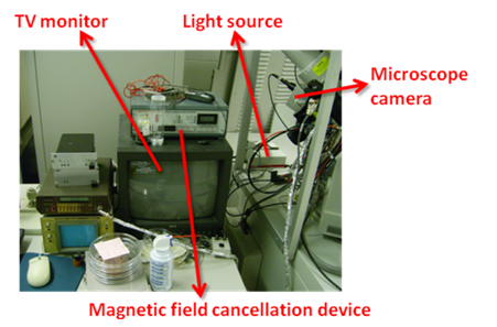
A microscope camera is installed in
the chamber. Before operation, set ‘Detector-OM’ in the menu.
Turn on the light source located on the backside of the machine,
and TV monitor. You can change zoom with the remote. Also,
camera angle can be adjusted slightly by physically tilting the
camera body. Turn off the light source before electron detector
activation.
For imaging and etching, vacuum level is not very important. However, for material deposition, it is critical. Maintain vacuum on the order of 10^-6 before deposition. Temporary pressure increase is normal just after GIS is open, since material crucibles have accumulated pressure. Of course, after several seconds, the pressure is stabilized. However, sometimes, this overshoots higher than beam operation pressure(about 1.3e-4). This will automatically turn off the beam. Therefore, before real processing, purge the GIS.
Since the chemicals are metal organic, they degrade after a while.(typically after a few years) In such a case, the materials must be replaced. GIS1(platinum) and GIS2(SiO2) use standard materials provided by FEI. You can ask FEI the service. However, GIS3(Cu) was custom installed setup. For copper deposition, “Cu(hexafluoroacetylacetonate)hydroate” was filled, with temperature setting of 50C. If you want to continue copper deposition, fill up the same material. Otherwise, you can clean the crucible, and fill the material you desire.
Sometimes, system shut-down or reboot is a good solution for electronic malfunction. There are three different types of them.
a. PC reboot
This only reboots PC, not the physical system. Therefore, it is a safe. When you face a malfunction, try this first.
- Turn off all beams.
- Close all the programs.
- Operate ‘Stop xP services’ in the desktop.
- Reboot PC.
- After booting, operate ‘Restart xP services’ in the desktop.
- Operate ‘xP 2.29’ in the desktop.
- Log in the program with ID(service), PW(service) and mark in
the ‘logon as a supervisor’.
- Operate ion-column IGP.
- Initialize the stage.
Note: When you press ‘HV’ button in electronic startup page, the system may require pressing physical ‘High Tension’ button. This ‘High Tension’ button locates besides system ON/OFF buttons.
b. Standby
This shuts down PC and peripheral electronic controls of FIB. Essential electronics like beam control are still on. If ‘a’ does not heal the problem, standby is a doable option.
- Turn off all beams.
- Click ‘source off’ button in electron startup page.
- Vent the chamber.
- Close all the programs.
- Operate ‘Stop xP services’ in the desktop.
- Shut down Windows.
- When “Now it is safe to turn PC off” message appears, press
‘Standby’ button once. It takes about 5~10 seconds before the
system turns off. Wait! Don’t press the button twice.
- To restart the system, press ‘ON’
button once.
- Following ‘a’, logon to xP program and initialize the system.
- Pump the chamber.
- Click ‘source on’ button in electron startup page.
This shuts down all the systems including beam control. Not recommended. You may need to start from bake-out process.
FIB is equipped with magnetic field cancellation device. However, this device turns out to degrade imaging quality. The reason is unclear. Anyway, currently, it is off.
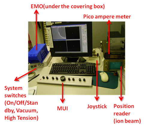
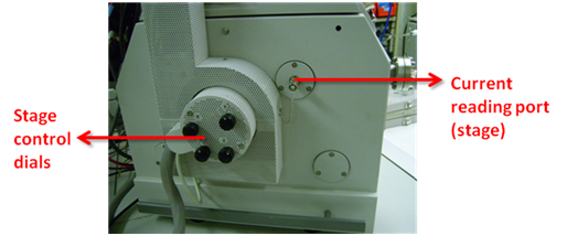
Current can be measured by pico ampere meter. Connect the coaxial cable to either ion beam blanker(to measure ion beam current) or stage(can measure all the incident charges. typically used to measure electron beam current).
Physical aperture strip degrades since they experience physical damages by collision with incident ions/electrons. This is particularly serious in ion beam strip. Check the numeric specification of aperture, and compare with measured current by pico ampere meter. If measured current is significantly large, it is time to change.
Electron gunhead is filled with SF6. Due to natural leakage, SF6 gas needs to be refilled regularly. Originally, the interval was about every 2~3 months. However, recently, the interval decreased to 1~2 weeks. FEI engineers suspect degraded gasket, but no obvious solution. At this moment, frequent refilling is the only thing we can do.
Once SF6 pressure drops below certain level, the machine turns off electron source, and shows alarm on the screen. Then, refill SF6 following the procedure, and turn on source afterward.
SF6 refill procedure
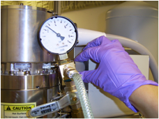
- Release the SF6 refill port(hand tighten) and connect the feeding unit. See the picture. The feeding unit is a custom-built tubing with fittings and regulators. It is stored in the bottom shelf of ESEM room.
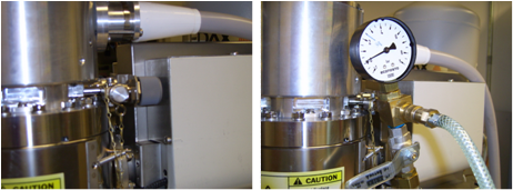
- Connect SF6 cylinder
to the feeding unit. SF6 cylinders are stored beside metal
evaporator.
- First, you need to purge the dead volume. Check the purging valve(the valve just below the regulator) in the feeding unit is CLOSED. Open SF6 cylinder to fill the dead volume. Then, close the cylinder. Open the venting valve to purge. After purging, close this venting valve. Repeat this twice.
- After purging, check the venting
valve is closed. Open SF6 cylinder. Open the needle valve as
shown in the picture, then SF6 fills the gunhead. The pressure
should be 2.5 bar.
- Close the needle valve. Close
cylinder. Open venting valve to release leftover gas, then
close.
- Detach the feeding unit from the beam column, cylinder from
feeding unit. Fasten refill port.
These beam sources must be replaced by FEI engineers.
Field emission gun(FEG) is always on. So, its lifetime is somewhat predictable. Typically it lasts 2~3 years. When FEG is first installed, emission current is typically less than 200 uA. If you don’t adjust extractor voltage, end-of-life FEG shows about 330~360 uA. Since this emission can be adjusted by extractor to some extent, this numbers are not very precise. However, it gives rough idea.
Ion source is on only when it is needed. So, the lifetime depends on the usage. Typical liquid metal ion source(LMIS) has 1500 hr specification, which is equivalent to 4800 uA-hr operation life. You can see the counter in ‘ion startup page’.
Replacing electron gun after baking
Some Ok window will come after the baking is finished (or may be aboart)
Place the electron gun with the alignment of green markers
refill SF6
Turn on electron gun.
Use for imaging.