Design of a low mass high torque brushless motor
Introduction
🤖 In the process of creating a discrete electromechanical motor, potentially, a multi descrete terrestrial robots (ground, hydro and aero), a need for a functional low mass motor is presented. To fullfill this need a new descrete electromechanical motor design was sought that would maintain the mass and maintain the torque output, when compare to not descrete motor. This project focuses on the design and following adaptable of using this decrete motor design for a current voxel robots.
Approach
In order to equally perform the current robot, several designs are considered. Each motor design is evaluated to find a design that has the best toque to mass ratio. A higher flux steel is also used for all design so that less stell is needed to carry the same amount of flux. This drop the mass of the total motor mass. With the cut in mass, the magnet thickness can be increased to produce more torque.
Using Maxwell equations and the desired layout of the motor, several defining moelding quation are formulated.
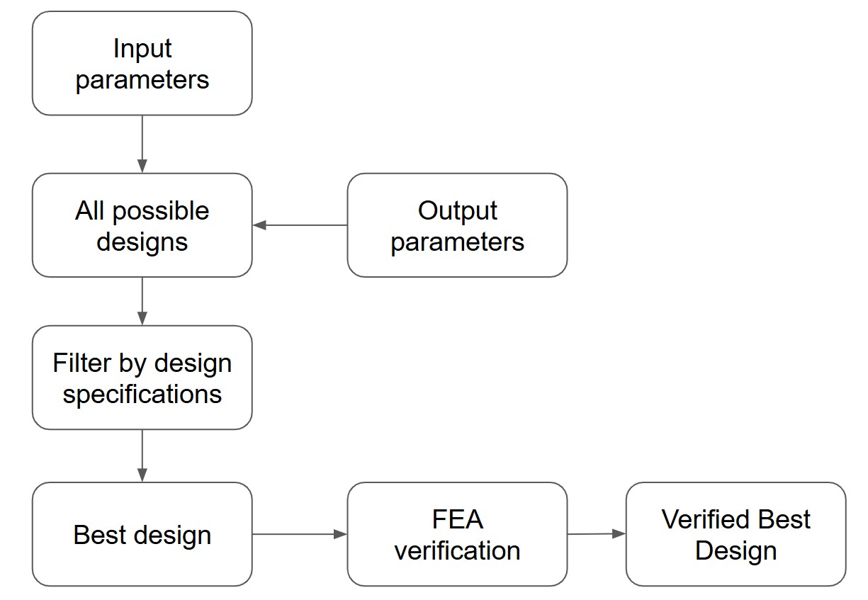
Design Flow Summary
- Choose input parameters
- Compute: T, R, Mass, P_D
- Filter: designs within 10% of target P_D
- Optimize: select lowest-mass design
- Verify: validate in FEA
Formulation
Input paremeters
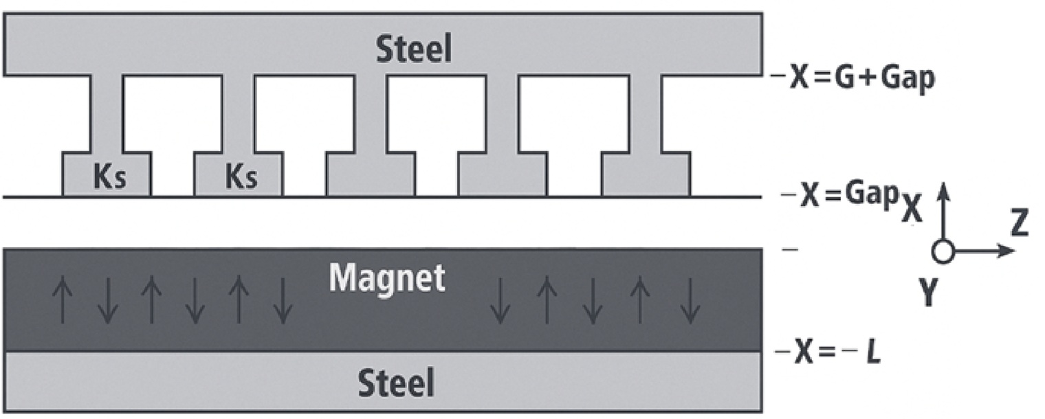
- Geometry
- Outer radius
R₅= 0.0635 m - Stator tooth length
G - Magnet length
L - Steel thickness
T - Axial length
W - Air gap
Gap= 400 μm - Slot fraction
δ∈ [0.2, 0.8]
- Outer radius
- Material Properties
- Magnet: Neodymium Boron (1.4 T)
- Steel: Hiperco 50
- Copper: density = 8930 kg/m³, conductivity = 6 × 10⁷ S/m
- Motor Targets
- Torque
τ= 40 Nm - Power dissipation
P_D= 2400 W - Packing factor
Pf≈ 0.5 - Number of pole pairs
P
- Torque
Core Equations
1. Torque
The torque generated by the motor is given by:
$$ \tau = \frac{4 R^2 \mu_0 k_s L W M_0}{\text{Gap} + L} $$
Where:
R = rotor radius,
k_s = surface current from the stator windings,
L = magnet thickness,
W = motor width,
M_0 = magnet strength,
Gap = air gap,
μ₀ = permeability of free space.
Torque Derivation: From Lorentz Force to Motor Torque
1. Lorentz Force Law
The force on a moving charge in a magnetic field is given by:
$$ \vec{F} = q (\vec{E} + \vec{v} \times \vec{B}) $$
For magnetic motors, we ignore the electric field and write: $$ \vec{f} = \vec{J} \times \vec{B} $$ where \( \vec{J} \) is current density and \( \vec{B} \) is the magnetic field.
2. Torque from Force
Torque is a force applied at a distance:
$$ \vec{\tau} = \vec{r} \times \vec{f} $$
For a cylindrical motor with radial magnetic field and tangential force: $$ \tau = R \cdot F_\theta $$ To get total torque, we integrate this shear force over the rotor surface.
3. Maxwell Stress Tensor
The shear stress on the rotor due to the magnetic field is:
$$ T_{r\theta} = \frac{1}{\mu_0} B_r B_\theta $$
where:
- Br = radial component of the magnetic field B,
- Bθ = tangential (circumferential) component of B.
This is the shear stress acting tangentially at the rotor surface due to interaction of radial and tangential components of the magnetic flux.
So the total torque becomes: $$ \tau = \int R \cdot T_{r\theta} \cdot dA = \frac{R^2 L}{\mu_0} \int_0^{2\pi} B_r(\theta) B_\theta(\theta)\, d\theta $$
4. Magnetic Field Models
Magnet-only field:
$$ \nabla \times \vec{H} = 0, \quad \vec{B} = \mu_0 (\vec{H} + \vec{M}) $$
Assume sinusoidal magnetization: $$ M(z) = \frac{4}{\pi} M_0 \cos(kz) $$
Current-only field:
$$ \nabla \times \vec{H} = \vec{J}, \quad \vec{B} = \mu_0 \vec{H} $$ Stator current: $$ K(z) = k_s \cos(kz) $$
5. Superposition Principle
Maxwell's equations are linear, so the total field is:
$$ \vec{B}_{\text{total}} = \vec{B}_{\text{magnet}} + \vec{B}_{\text{current}} $$
6. Compute Torque
Assuming: $$ B_r = \mu_0 M_0 \cdot \frac{L}{\text{Gap} + L} \cos(kz), \quad B_\theta = \mu_0 k_s \cos(kz) $$ Then:
$$ \tau = \frac{R^2 L}{\mu_0} \int_0^{2\pi} \mu_0 M_0 \cdot \frac{L}{\text{Gap} + L} \cdot \mu_0 k_s \cdot \cos^2(kz) \, d\theta $$
Average of \( \cos^2(kz) \) over a full cycle is \( \pi \), so:
$$ \tau = \frac{\pi R^2 \mu_0^2 k_s L^2 W M_0}{\mu_0 (\text{Gap} + L)} = \frac{\pi R^2 \mu_0 k_s L^2 W M_0}{\text{Gap} + L} $$
Now factor in the waveform coefficient \( \frac{4}{\pi} \) from the magnetization:
7. Final Torque Equation (Complete Form)
$$ \tau = \frac{4 R^2 \mu_0 k_s L W M_0}{\text{Gap} + L} $$
2. Mass of Motor
The total mass of the motor is calculated by summing the volume of each concentric cylindrical region, multiplied by its material density.
General volume of a hollow cylinder:
$$ V = \pi (r_{\text{outer}}^2 - r_{\text{inner}}^2) \cdot W $$
Motor Mass Components
- Stator Back Iron (outer steel shell):
- Rotor Back Iron (inner steel shell):
- Magnets (rotor permanent magnets):
- Stator Tooth Region:
$$ M_1 = \rho_{\text{steel}} \cdot \left[ \pi (R+G+T)^2 - \pi (R+G)^2 \right] \cdot W $$
$$ M_2 = \rho_{\text{steel}} \cdot \left[ \pi (R+L)^2 - \pi (R - L - T)^2 \right] \cdot W $$
$$ M_3 = \rho_{\text{NdFeB}} \cdot \left[ \pi R^2 - \pi (R - L)^2 \right] \cdot W $$
This region is partially steel and partially copper, depending on the slot fill fraction \( \delta \).
Steel part:
$$ M_4 = \rho_{\text{steel}} \cdot \left[ \pi (R+G)^2 - \pi R^2 \right] \cdot (1 - \delta) \cdot W $$Copper part:
$$ M_5 = \rho_{\text{copper}} \cdot \left[ \pi (R+G)^2 - \pi R^2 \right] \cdot \delta \cdot W $$Total Motor Mass
Adding all five components:
$$ \begin{aligned} M =\ & \rho_{\text{steel}} \cdot \left[ \pi (R+G+T)^2 - \pi (R+G)^2 \right] W \\ &+ \rho_{\text{steel}} \cdot \left[ \pi (R+L)^2 - \pi (R - L - T)^2 \right] W \\ &+ \rho_{\text{NdFeB}} \cdot \left[ \pi R^2 - \pi (R - L)^2 \right] W \\ &+ \rho_{\text{steel}} \cdot \left[ \pi (R+G)^2 - \pi R^2 \right] (1 - \delta) W \\ &+ \rho_{\text{copper}} \cdot \left[ \pi (R+G)^2 - \pi R^2 \right] \delta W \end{aligned} $$
Parameter Definitions
- R: Rotor radius (center of magnet arc)
- G: Stator tooth height
- T: Steel thickness
- L: Magnet thickness
- W: Motor axial width
- \( \delta \): Slot fill factor (copper fraction)
- \( \rho_{\text{steel}}, \rho_{\text{NdFeB}}, \rho_{\text{copper}} \): Densities of each material
3. Resistance
Computes heat loss
We start from the basic formula for resistance:
$$ R = \rho \cdot \frac{\ell}{A} $$ Where:
- \( \ell \): total length of copper wire
- \( A \): effective cross-sectional area of copper per current path
1. Total Wire Length
The total length of copper wire in the motor is estimated as:
$$ \ell = (2\pi R + 2W) \cdot 3P $$ This accounts for:
- \( 3P \): total number of coil sides in a 3-phase machine with \( P \) pole pairs
- \( 2\pi R + 2W \): approximated average length per coil turn (circular + axial)
2. Slot Area
The total slot area available for winding is:
$$ A_{\text{slot total}} = 6\pi R G $$ Only a portion of this is filled with copper, so the effective copper area is:
$$ A = P_f \cdot 6\pi R G $$ Where \( P_f \) is the copper fill factor (typically 0.3–0.6).
3. Final Resistance Formula
Substitute \( \ell \) and \( A \) into the resistance formula:
$$ R = \rho \cdot \frac{(2\pi R + 2W) \cdot 3P}{P_f \cdot 6\pi R G} $$
- \( \rho \): Copper resistivity (≈ \( 1.68 \times 10^{-8} \ \Omega \cdot \text{m} \))
- \( R \): Rotor radius [m]
- \( W \): Stack width [m]
- \( G \): Slot height (stator tooth length) [m]
- \( P \): Number of pole pairs
- \( P_f \): Fill factor (copper fraction of slot area)
4. Power Dissipation
This derivation captures how geometric and material properties contribute to copper heat losses in the motor windings.
Step 1: Base Expression from Joule Heating
Start with:
\[
P_D = I^2 R
\]
where \( I \) is total current and \( R \) is winding resistance.
Step 2: Approximate Total Current
From the surface current density definition:
\[
I \approx 2 k_s R W
\]
Step 3: Estimate Resistance from Geometry
Using:
\[
R \approx \frac{\rho \cdot l}{A} \propto \frac{(2\pi R + 2W) \cdot 3P}{6\pi R G P_f}
\]
and substituting \( \rho = \frac{1}{\sigma} \), the conductivity of copper.
Step 4: Final Power Dissipation Form (Eq. 2.58)
\[
P_D = \left( \frac{W + \frac{\pi^2 R}{2P}}{G \delta \sigma p_f} \right) \pi R k_s^2
\]
Explanation:
- Numerator: Total effective wire length: \( W + \frac{\pi^2 R}{2P} \)
- Denominator: Conductor cross-section area: \( G \delta \sigma p_f \)
- Scaling: The term \( \pi R k_s^2 \) incorporates the square of the surface current density and motor size.
This compact and normalized form estimates copper losses from motor geometry and material constants.
Ref: https://dspace.mit.edu/handle/1721.1/75658
Motor Design Calculator
General Motor Geometry
The fill factor 𝑝𝑓 p f is the fraction of the motor's slot area that's actually filled with copper wire. It ranges from 0 to 1. A higher fill factor means more copper, less resistance, and better efficiency. Typical values are around 0.4–0.6 depending on how the windings are made.
A pole pair is one north and one south magnetic pole on the rotor. The number of pole pairs, denoted by 𝑃 P, affects how the motor converts electrical frequency into mechanical rotation. More pole pairs generally mean higher torque but lower speed for a given frequency.
Torque Calculation
A strong neodymium magnet typically creates about 1.4 Tesla of magnetic field.
We can calculate its magnetization using the formula:
M₀ = B / μ₀
- B = 1.4 T (magnetic field)
- μ₀ = 4π × 10⁻⁷ H/m (permeability of free space)
So:
M₀ = 1.4 / (4π × 10⁻⁷) ≈ 1.1 × 10⁶ A/m
This means a typical neodymium magnet has a magnetization of about 1.1 million A/m.
eg. Neodymium Boron magnets capable of creating a 1.4 Tesla flux.
Surface current density (ks) tells us how much electric current flows along each meter of the stator surface. It is measured in amperes per meter (A/m).
Magnet Thickness Derivation
Hgap tells us how strong the magnetic field needs to be in the gap where torque is created.
Hsteel is the magnetic field intensity in the steel parts of the motor, such as the stator and rotor core. It is measured in amperes per meter (A/m).
It reflects how much magnetic force is needed to push the magnetic flux through the steel, which has much higher permeability than air. Lower Hsteel means better magnetic performance and lower losses.
Hmag is the internal magnetic field intensity inside the magnet material itself. It’s measured in amperes per meter (A/m) and is usually a negative number because it opposes the magnet's own magnetization.
This value is used in the magnet thickness equation. Stronger (more negative) Hmag allows the magnet to support more field in the air gap without saturating.
Material Properties
Resistivity (ρ) tells us how much a material resists electrical flow. It’s measured in ohm-meters (Ω·m).
Lower resistivity means better conduction and lower power loss. Copper has very low resistivity, which is why it's widely used in motor windings.
ρsteel is the density of steel, measured in kilograms per cubic meter (kg/m³). It tells us how heavy a given volume of steel is.
ρmag is the density of the permanent magnet material, given in kg/m³. It shows how heavy the magnet is for each cubic meter of volume.
ρcu is the density of copper, in kg/m³. It tells us how heavy copper is, which is important for calculating the mass of motor windings.
Current-Based Performance
k is a design constant (in amperes) that relates to how much current is required to generate a certain amount of force or torque in the motor.