Making the parallel cable (The EASY one!)
-
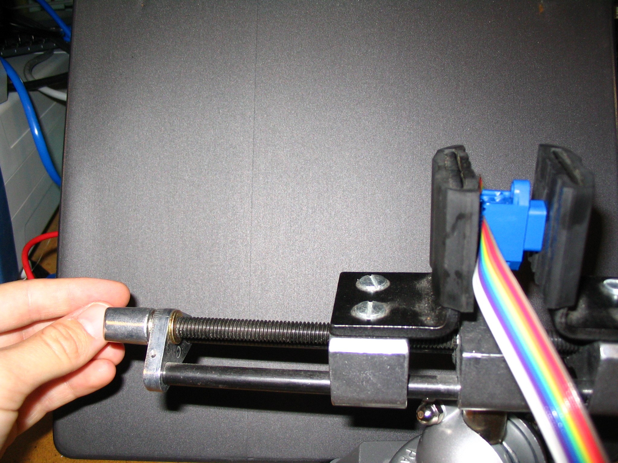
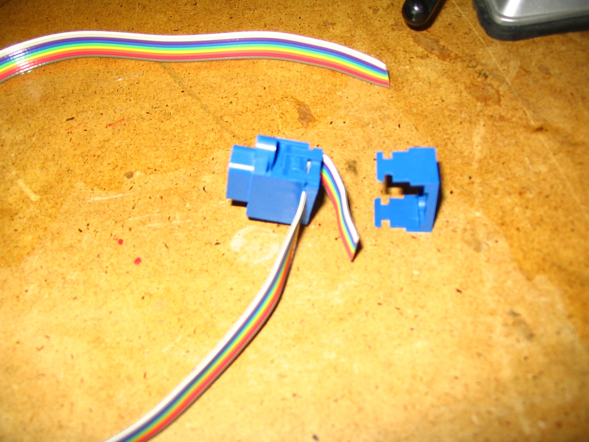
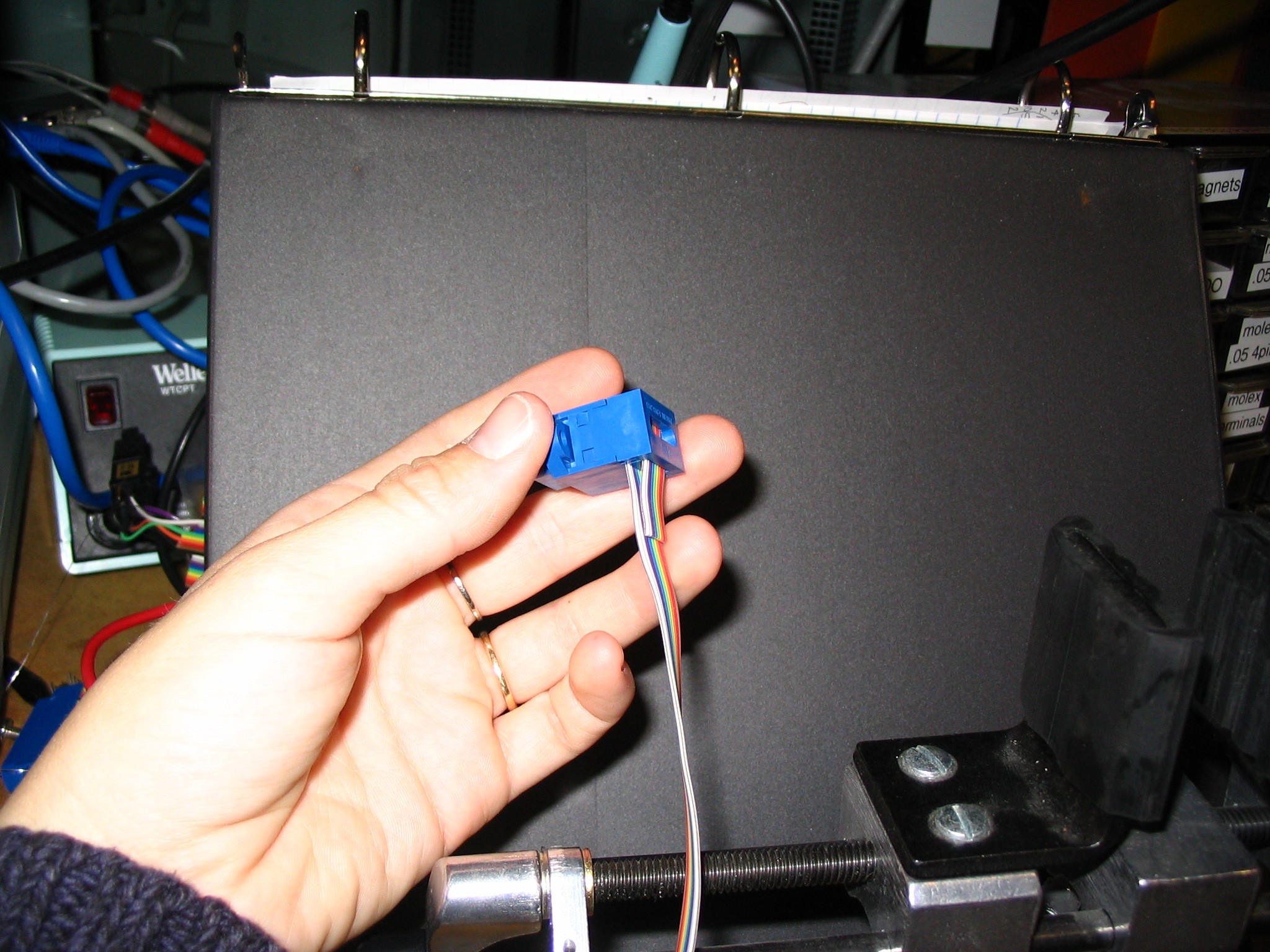
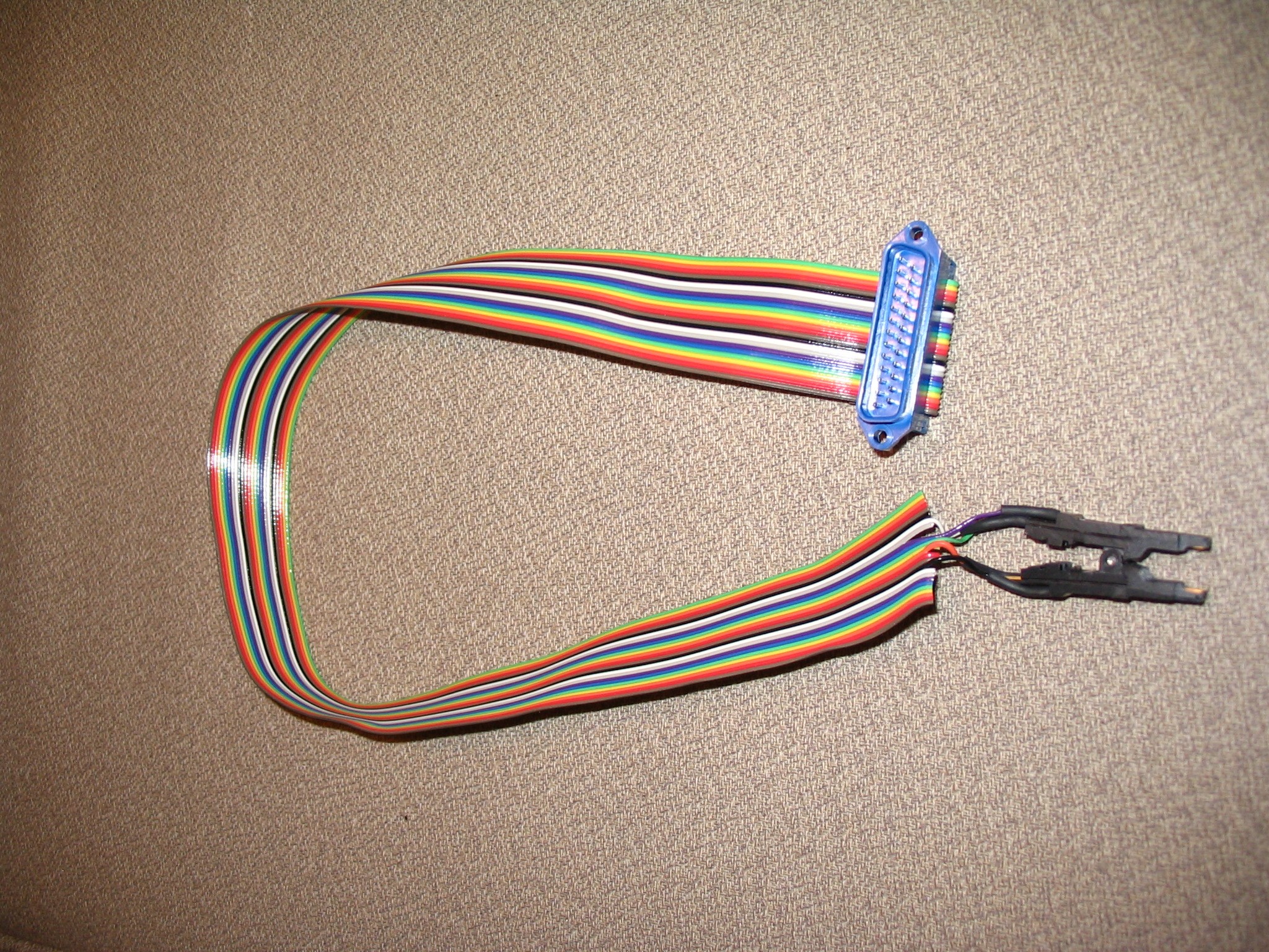
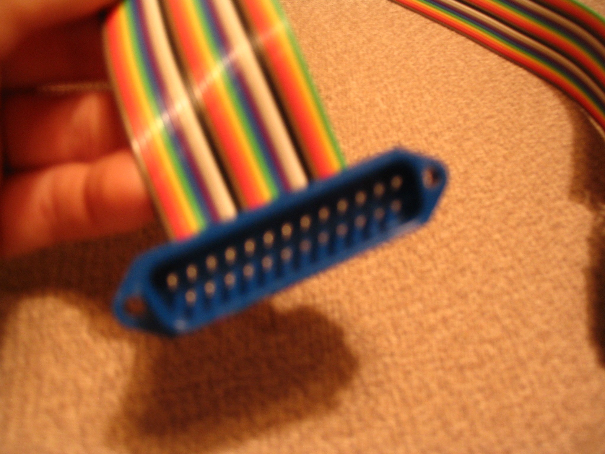
Get a length of rainbow-color-coded, 25-wire ribbon cable and feed it through a blue DB25 male connector. Clamp the assembly in a vise and squeeze it (by tightening the vise) until you hear two faint clicks indicating that the connections are made between the connector and the wire. When you finish squeezing, put a strain-relieving blue 'cap' on the connector. See pictures below but NOTE that the picture shows a different-size cable and connector than what you have.
-
The pins on the connector and the wires in the cable are both numbered 1-25. Pins 1-13 are in the longer TOP row on the connector, and pins 14-25 are in the shorter BOTTOM row. If you are holding the cable/connector assembly so that you are looking at the pins (and pins 1-13 are in the longer, top row and 1 is at the upper left -- like this), then wire 1 is the leftmost wire. The 25 wires are numbered from left to right.
-
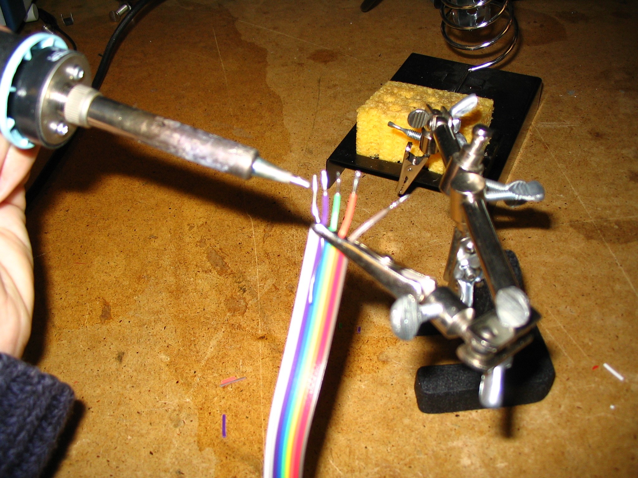
Use the cable layout (you can find one for 2005 hello world chips on this fab website) to figure out which 4 wires from the cable you will use. Separate a few inches of those wires from the rest of the cable (they peel apart easily) and cut off the wires you will not use. Strip about an inch of the ends of the wires you are using, and "tin" them with a little solder. You may want to trim them a bit shorter now so that just enough exposed wire is available to make the connections in the next step. Put a piece of heat-shrink-wrap on each wire NOW - you won't be able to put it on after you solder on the programming clip!
-
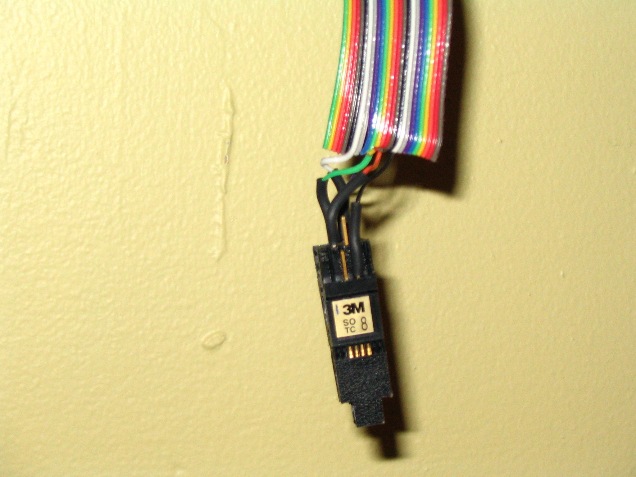
Get a programming clip, decide which of its connectors is number 1, and mark it somehow for future reference. If you hold the clip so that 1 is on the upper left, then 8 is on the upper right (with 2-7 in between). Solder the wires of the cable to the connectors on the programming clip according to the cable layout you are using.
-
The cable is almost done! You can test the electrical connections using a multi-meter - do this if you think there's any small chance that you may have connected the wrong wires, or done a poor soldering job. (admit it, there's a chance.) Set the meter to beep when an electrical connection is made, connect the arms of the programming clip to the corresponding pins on the parallel connector, and hope for a beep.
-
Slide the heat-shrink-wrap down to cover the soldered connections between the wires and the programming clip, and use the heat gun to shrink them in place.
-
You may want to take the spring out of the clip to make it easier to use. The best way to do it is to use something small and pointy to push out the pin holding the two halves of the clip together, removing the spring (which should be easy with the pin removed), and then replacing the pin.
-
All done - test the cable by trying to program a chip with it! (Note - to program a chip and verify that it worked, you'll need a serial cable as well, in most cases).