Eagle Getting Started
(MAS863 F’03)
Get
Eagle PCB Layout Editor (free version)
PCB Assignment
Let's build a simple high-pass
filter!
Components (in libraries):
1 resistor
1 capacitor
1 ground
2 solder pads (I/O
ports)
1) Start Eagle
When you start
Eagle the Control Panel should pop up.
2) Create New Schematic
3) Add a resistor
-
Go to the Control
Panel. Expand Libraries -> discrete.lbr
-> RESUS-5. The library folders are organized by functionality and by
manufacturer. Some symbols may be European and some may be US. RESUS-5 is the US
symbol for a resistor.
When RESUS-5
is selected two figures will appear. The figure on the left is how the resistor
will look in the schematic view and the figure on the right is how the resistor
will look on the board layout.
When selecting a
component in a library you may notice one of two symbols next to the name of the
part. A parts symbol
 means that Eagle provides both the schematic and layout for that part. The other
symbol is a layout symbol
means that Eagle provides both the schematic and layout for that part. The other
symbol is a layout symbol
 which means that you need to make this component.
-
Select ADD
then left-click (on mouse) to place the part. Another window may pop up, just
select Cancel. Press escape (Esc) to exit out of the mode.
-
Set the name of the
resistor by choosing the Name button
 . Set the
value of the resistor to 10k with the Value button
. Set the
value of the resistor to 10k with the Value button
 .
.
-
To move the part
you can select the Move button
 .
.
-
To rotate the part
you can select the Rotate button
 and
click on the object you wish to rotate.
and
click on the object you wish to rotate.
4) Add a capacitor
5) Add Ground
6) Add Input/Output ports
7) Connect (wire) the components
-
To connect the
components use the Wire button
 . Hit the
escape key to get out of the wire mode. To create an explicit junction use the
Junction button
. Hit the
escape key to get out of the wire mode. To create an explicit junction use the
Junction button
 .
.
-
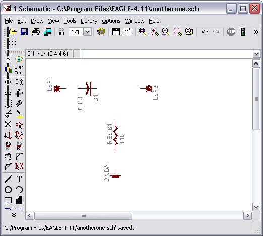
Here is an image of
the circuit wired up in the schematic.

Make sure to save your schematic!
Now you are ready to go to the board!
Delete: To delete,
click on the (X-button) Delete button
 then
click on the object you want to delete.
then
click on the object you want to delete.
Where
is/are…
Resistors and capacitors? discrete.lbr
Power and Ground?
supply1.lbr
Input/Output ports (solder pads)?
solpad.lbr
How do I...
Add a new library?
Additional
Resources
Cadsoft
Eagle Tutorial & Manual
Modeling/Simulation
Tools
Ngspice
(interacts directly with Eagle)