Hello World 2 Circuit Board: Serial IO and Led's
This assignment is to modify the circuit from last week's assignment to add the ability to receive data over the serial connection as well as control an LED.
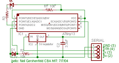
This is the schematic of the circuit. A zener diode is used to bring the -12 to +12 voltage swing of serial line into (roughly) the rail to rail range of the tiny13 to keep from damaging the input pin circuitry.
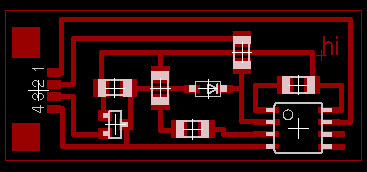
And here is the board layout:
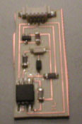
And the board, stuffed with the components (hmm, with the led's I used, the cut off corner connects to positive...?):
Slightly modified versions of the example asm files for echoing characters and blinking that work on my tiny13 setup.
hello1.15.echo.j.asm (changed from tiny15 to 13, clock speed to default, bit delay to 17, set stack pointer to top of ram)
hello2.blink.j.asm(changed from tiny15 to 13, bit delay to 17, set stack pointer to top of ram)
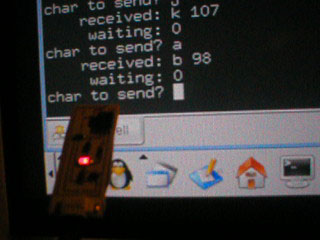
Click the image below for a video of the board working, showing off input, output and LED control - it recieves a byte over serial, adds one and sends it back, then blinks the LED.
edit