edit
Chris Wasshuber's MAS 863 Blog
Contents
Quick Introduction
First Thoughts on a Project
Assignment 1 - Model, animate and render the final project: desktop tool
Assignment 2 - Invention kit from cardboard or acrylic: ball track
Assignment 3 - Waterjet cutter: flexures
Assignment 4 - PCB manufacturing and stuffing
Assignment 5 - cables and more PCB
Assignment 6 - how to measure (almost) anything
Assignment 7 - 3d scanning/printing - Lego e-bricks
Assignment 8 - output: stepper, LCD, video, sound
Assignment 9 - injection molding, shrinking Lego e-bricks
Final Project - Personal Fabricator
Quick Introduction
I am in my second year in business school at MIT Sloan. Before coming to MIT I worked six years in R&D at Texas Instruments developing semiconductor devices and processes, mainly for the latest 45nm CMOS technology. My PhD was in nano-electronics (single-electronics to be precise) and I have kept up with the field and hold a few patents in this area. I also wrote a book in case anybody is interested ("Computational Single-Electronics").
Being an entrepreneur at heart I have started five years ago an online business publishing and selling electronic books, or so called ebooks, in the genres of gambling, games and magic. If you have an interest in this area I am always happy to chat, or even better check out my site Lybrary.com and spend all your allowence there :-).
First Thoughts on a Project
I have thought about personal fabrication throughout the summer. I read Neil's book "Fab" and have before that spent a semester thinking about user innovation and the implications of powerful tools and how these will change the future, which leads necessarily into personal fabrication. Three aspects are most interesting to me: reduction of tool cost, self-replication and tool versatility.
With reduction of tool cost I mean the challenge of further reducing the cost of personal fabrication tools. What can be done to further reduce the cost? One interesting thought is to use focused sun light to cut material, sort of as a low cost replacement for expensive lasers. (Interesting side note. A quick online search I did a few weeks ago to find the lowest source for a cutting laser yielded a place in Eastern Europe that sold 30W lasers for $800. I would be interested to find out if that is about the cheapest available today.) One other idea to reduce the cost, which is likely to become my semester project for this class, is to use a 'turntable' design as 'x-y' table. More on this further down.
Self-replication is something really cool. The fact that a tool could self-replicate would imply low cost, because once you have one tool, you can make as many as you want yourself. Although I think we are still far away from a complete self-replicating versatile tool, I am convinced we could achieve a 90% self-replication which would help in reducing the price and spreading personal fabrication.
Tool Versatility is a big issue, because I see big inefficiencies in taking a piece and moving it from one tool to the other, including setup costs and scheduling cost. Most of the tools we will be using are very similar in basic function. An x-y or x-y-z positioning system and a machine head of some sort, be it laser, waterjet, milling, cutting, ... It ought to be possible to build one positioning system with several heads. This would further reduce total cost, because several parts of the tool only need to be there once, and it would open new capabilities. Take for example the manufacturing of circuit boards. We will mill out the board, then manually place components and solder them in place. If the milling tool would have a pick-and-place head, and a soldering head, it could do all of that for us.
These thoughts lead me to my project. It is probably a bit ambitious, but maybe somebody would like to team up and join efforts to accomplish this.
Thoughts on CAD
I installed Blender on my Apple and it works fine, but it has a bit of a learning curve. I am still struggling with fairly simple tasks. Seth introduced us to Sketchup which seems to be an order of magnitude more productive. In a few seconds one can have a fairly complex object. I hope we can figure out the license issues with Sketchup. For now I will stick to Blender.
Assignment 1 - Model, animate and render the final project
I choose to model the turntable tool although I am more inclined to do the page turner together with Sam. It took quite a while to learn the basics in Blender and I am still confused by some weird behavior. I failed to extrude a screw and to add particle effects.
Turntable Tool
The two big discs, the tool-disc and the sample-disc, are essentially two big gears which are turned by a stepper motor and screw from the perimeter (one motor with screw is shown in the animation above). If we assume a tooth every millimeter for the gear and a 400 step per rotation stepper motor, then we can achieve a spatial resolution of 2.5 micrometer.
Assignment 2 - Invention kit from cardboard or acrylic
I quickly settled on the material, cardboard. Since my father worked in a paper factory, I grew up to appreciate paper on a very different level than most people do. However, I had a hard time to come up with a unique design idea. Should I design a general kit, or something specific? On one hand it would be nice to come up with a very general kit which allows one to do a lot of things, but this would require fairly small elements, so small that the shape of the individual element is on a much smaller scale than the objects to be built. Cardboard doesn't seem to be the ideal material for such a small element. I finally decided to build a ball track kit, for my son.
My first design on paper used fairly complex pieces. In the second design iteration I figured out how to simplify the elements and settled on two elements. One is essentially a square which is used to build towers and the other one is a long stretched rectangle to form tracks for the ball to roll on. (In the end I added a third element, which is not
essential, but it makes a bit better looking tracks.)
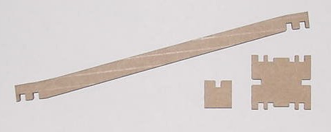
I installed NeoOffice on my Apple, but figured out that the svg created does not work with cam.py. This required me to design everything on the computer connected to the laser cutter. I am used to millimeters instead of inches. Luckily the draw utility can be changed in Tools->Options to millimeter. For the cutouts I used 4 mm and I set an undercut in cam.py of 0.011 (after some experimenting). After my first cut I realized I made one crucial error in my design, which blocked the ball from rolling freely along the tracks. The fix was straight forward and the second cut was perfect.
I have not yet tested it on my son, but I built at 1am a little track and tested it. Works wonderfully. One can build forks as well as places where two tracks join. For the aluminium ball the track inclination is great, for a heavier marble it is a bit too steep. The marble zips through it too fast.
When I formed a ball from aluminium foil, I realized that such a foil is actually a wonderful modelling material. It starts out as a very soft and formable sheet, but once crumpled and pressed it becomes quite hard. Could one build a machine which could crumple a sheet of metal foil into an arbitrary shape? Interesting idea!
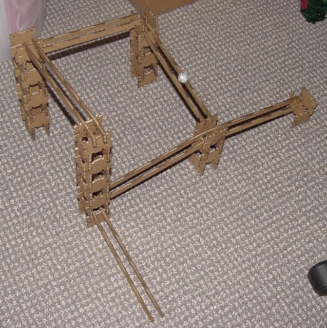
My son bugged me the whole time because he saw the cardboard pieces lying around. So the other day we played with the ball track. The amazing experience was that after a few minutes of fooling around, my son invented a new combination of elements which I haven't thought of. Based on this element we built a pretty cool track.
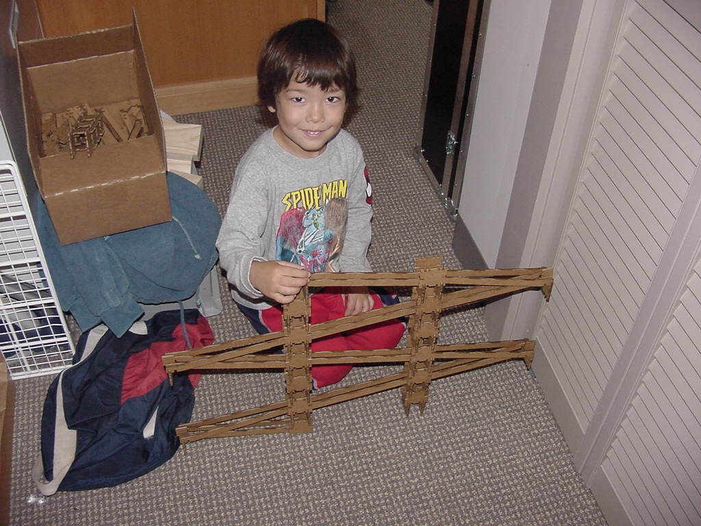
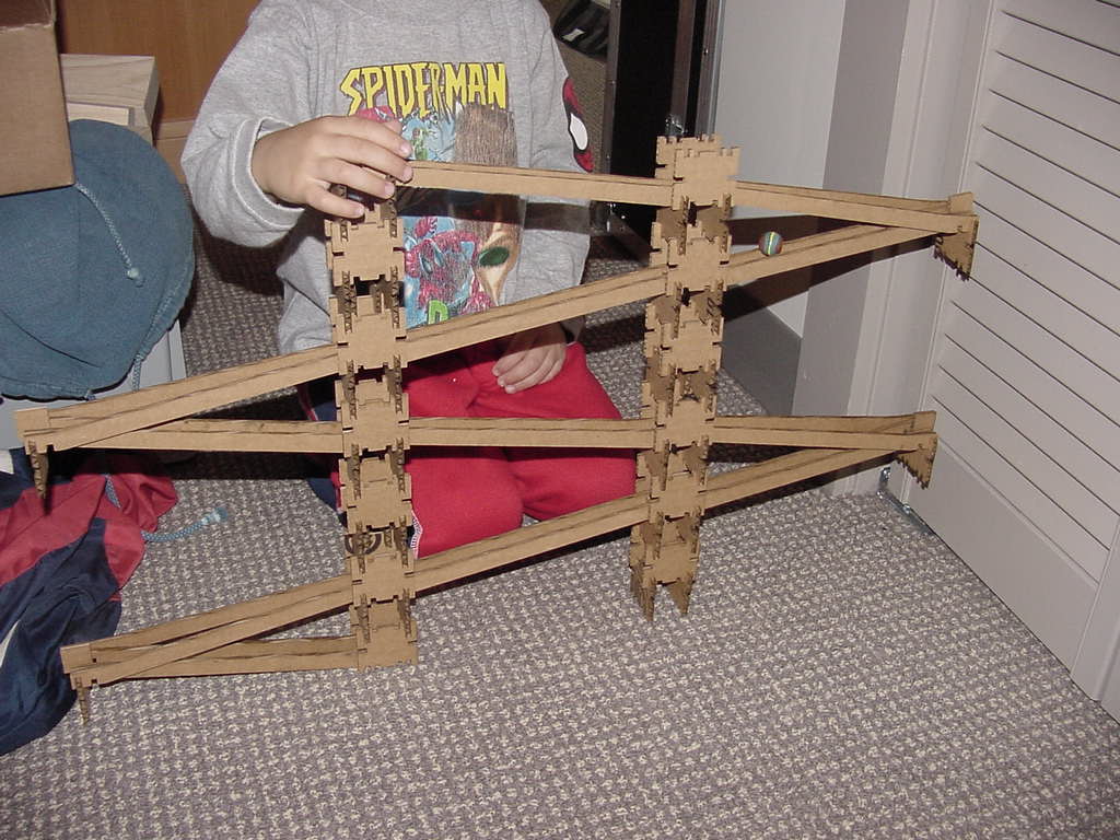
The elements on the end are the invention my son Stefan made. The top pair of rails bend away from each other, so that the ball eventually falls through to the lower track and reverses his direction. The ball picks up so much speed that we had to put in little stoppers at the very end.
The invention-kit was truely an 'invention' kit. Over the last days when I came home my son greated me with "Let's play Kugelbahn" (Kugelbahn is German for ball-track).
Assignment 3 - Waterjet cutter
I decided to use this assignment to get started on my final project, the turntable. The turntable consists essentially of two offset discs which can be turned individually. Each disc is a big gear wheel which is turned by a worm and the worm is directly attached to a motor shaft. My plan was to cut out one of the gear wheels with the waterjet cutter. I used the free design tool from emachineshop.com because it has a gear design feature. I used a gear with 20 degree pressure angle, pitch 16 and 144 teeth. This resulted in a roughly 9" disc, about the size I intend to make the turntable. I exported the drawing to a dxf file and imported it into Omaxlayout.
The cutting with the waterjet was straight forward. I first cut it out from a piece of scrap plastic and then from a 1/8" aluminium sheet. I used the highest quality cut (5). The edges look nice but they are not finished cuts. I wonder how one can further smooth the edges.
The gear will be mounted on a lazy sousan. I have orderd two lazy susans (one for $9) from McMaster to test the concept.
Neil suggested I look into flexures (compliant mechanisms) to replace the bearings in my desktop tool. The big advantage of flexures is that they are cut out of a metal sheet (ex. Al) and do not require balls or other bearings. This means it is a big step towards self-replication. It is much easier to cut out a flexure than to produce and assemble a ball bearing. It also means no lubrication, backlash and noise which can be a problem with conventional bearings. A flexure is basically a set of beams which can bend and thus provide movement in certain directions, but restrict it in others. Talking to Manu who has done quite a bit with flexures and searching online, I have acquired a basic understanding of flexures.
I have started to dabble in designing a flexure for my tool. The first step is to design a flexure which allows 2" linear motion in one direction, and restricts it in the other two spatial dimensions. The challenge is to keep the flexure as small and compact as possible, and restrict movement in the other spatial directions. This flexure should be the z-elevator for the tool head - to move the tool head up and down. If this is successfull I will try to design a similar flexure with a range of 6". Two of these would replace the two turntables or the classic linear bearings used in such tools. Alternatively one could build a flexure which allows movement in two directions to function as xy-table.
Using the idea of nested parallelograms, one can build fairly compact flexures. The basic idea is to fold a long beam, which would provide enough range for the motion, into a zig-zag shape to pack it into a smaller space. The problem that is created is that this structure will become less rigid in the other directions, particularly in the direction perpendicular to the sheet the flexure is cut out. This could be countered to some degree by using a thicker piece of metal, but that increases cost and there are processing limits and material property limits to this.
My best idea so far is to use the third dimension to link 2, 3 or 4 of these flexure sheets together. Some movable beams in these flexures can be rigidly linked with other beams in other flexures to insure their simultaneous movement as well as further restrict movement in the undesired directions. I hope this results in a rigid structure which only allows movement in one linear direction.
This is my first generation flexure
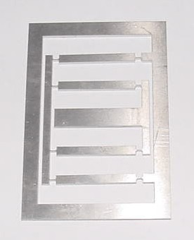
It is a simple double parallelogram cut out of a 1/8" Al sheet. The thinnest parts are about 0.7 mm thick. It provides a total travel of about 8 mm. This is quite a bit away from 2". The second generation design is smaller in size but provides about 20 mm travel. I made three of these to connect them into a U-shape to improve on the stiffness in the directions the flexure should not move.
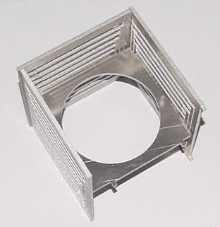
This is already pretty good. It is quite stiff in the x and y direction and provides almost 1" travel in the z direction. With a bit of optimization I think I can squeeze out one or the other milimeter in total travel. For the final version I think I am going to cut this out of a 1/4" sheet to give it still more stiffness.
Cutting out these flexures was a real pain, because the loose pieces get caught in the foam ring of the waterjet head and if caught often completely destroy the flexure. I had to stop everytime a loose piece was created to remove it, and even then it destroyed one of the pieces. It was also very important to make sure the head moves the least amount from cut to cut to reduce the likelyhood that something got caught. Ultimately one would like to cut these flexures with an EDM (electric discharge machine). Since I designed it with the emachineshop.com tool, it was simple for me to get a price. The structure depicted above would cost $700 cut with an EDM out of 1/4" Al 6061. It pays to have your own tools.
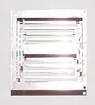
The challenge to get as much range of motion out of a small piece got to me and I designed further variations to omptimize the flexure. The one shown below has a range of 3.7 mm and is not larger than the versions shown above. This is a real improvement. It could have a range of about 4.5 mm, but the cut was not uniform enough to realize it.
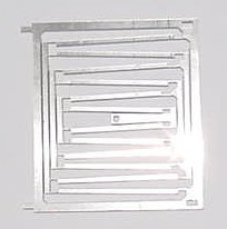
The biggest challenge was to prevent vibrations during the waterjet cut. One has to surround the structure with weights. This flexure was cut out of 1/4" Al. Something went wrong with the cut, because the backside has a very rough edge, very different from earlier cuts I did. With a bit more optimization and non-linear distribution of gap space, I think I can achieve the 2" range I set out to get. Although I cut this one out of 1/4" thick Al, its stiffness in z-direction is still quite poor.
Assignment 4 - PCB manufacturing and stuffing
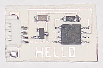
Milling with the Modela was ok. Soldering the SMD components was a bit of a challenge. I have done lots of soldering in the past, but never SMD components. After a few contacts it was quite ok. It is not my best solder job, though.
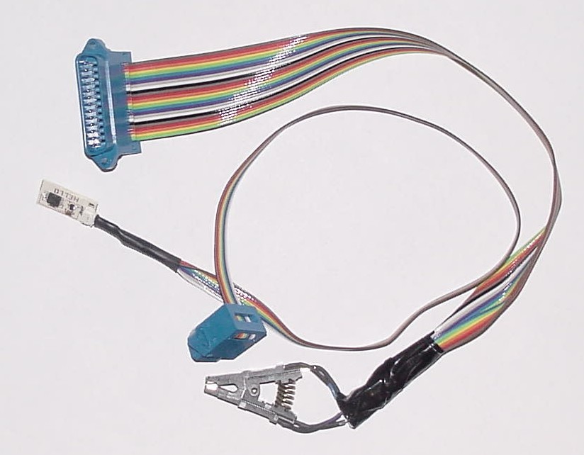
I tested the circuit, but kept getting a verification error. I am not sure if this is due to the cable, or if the processor is faulty, or if my soldering is bad. I also tried to make one of the cables, the one with the tiny serial connector, but after almost two hours, I gave up. This tiny serial connector brought me down.
Assignment 5 - Cables and more PCB
With some tips (ex. soldering the cables to the connector) I managed to make the two cables. Resistance testing from pin to pin gave good results.
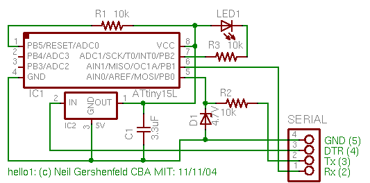
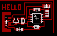
Eagle installed fine on my Apple. Here are the changed schematic and layout.
My goal is to have my Apple ready for programming the ATtiny13. Avrdude is causing problems. Actually, gcc and the compilation of binutils does not work properly. I spent quite some time trying to fix this but without success.
Assignment 6
Assignment 7 - 3d scanning/printing - Lego e-bricks
I scanned in a Lego piece and one of my flexures. But both did turn out to be fairly bad scans. I suspect that the smooth surfaces caused reflections which produced many spurious points. Since these scans were from my point of view unsatisfactory and we ran into the problems with the 3d-printing machines, I decided not to print out any of my objects. I understand the scanning and spent several hours scanning, cleaning up scans and combining them. Printing them out is more or less straight forward, if the machines work properly.
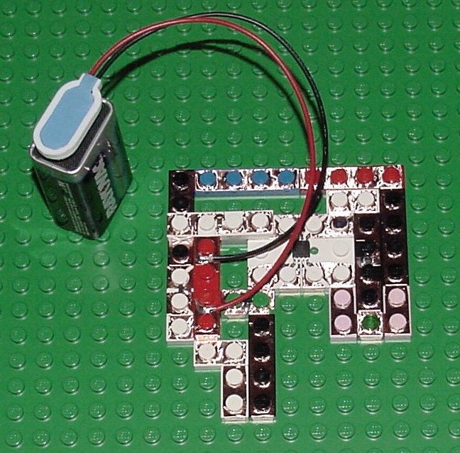
The rest of the time I spent working on my Lego e-bricks. It was a full success. I still have problems contouring my DXF files with cam.py, but I cut my design without contouring on the vinyl cutter, which worked ok. The best process is to cut the copper foil on the vinyl cutter, then to remove the unnecessary copper foil pieces, then to solder the components onto the copper foil, and then to attache the foil to the lego piece. The attaching part can be a bit tricky if we are talking about a component with several legs (ex. the 8-pin tiny13). Then I placed the Lego e-bricks on a base plate to create our initial hello world circuit.
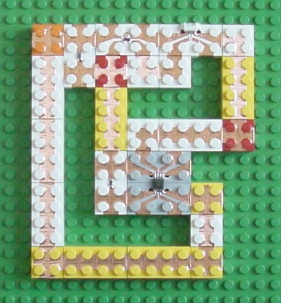
I tested the connections, which were typically in the 0.5 Ohm range. Then I hooked it up to the lab PC and it worked the first time. Great. This is now a wonderful fast way to create a circuit and test it. I will need to make a few more e-bricks with other components such as LEDs, zener-diods and transistors. Also more simple zero-ohm connectors of various kinds are necessary to build a bit larger circuits. Then I was curious how good the connection really was. I lined up 11 e-bricks in series to get 10 connections as seen in this picture.
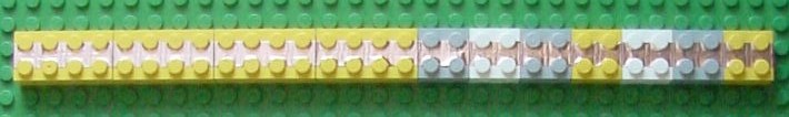
The resistance was still less than 1 Ohm. Then I started to bend the base plate, which is flexible, but I still got the same low resistance, which was surprising to me. But it turns out that even in the bent state, there is contact at the bottom where the Lego bricks lock into the base plate. So this system results into fairly stable connections. I am wondering about the longevity of these connections, though.
I could also get an IoGear USB-to-Serial adapter installed on my Mac. I further installed the Serial module for Python and could run rx.py successfully reading the output sent by the above hello world circuit. I am now trying to program a bootloader for the tiny13.
Assignment 8 - output: stepper, LCD, video, sound
I decided to work on controlling a stepper motor and to do everything with my Lego e-bricks. I spent quite some time to make several more e-bricks with sockets and plugs. Before I built the stepper control circuit, I built the serial receive/transmit circuit and spent considerable time getting it to work. I encountered a lot of erratic behavior, which was caused by two effects. One was to get the correct bitdelay, which in my case turned out to be 18. The second problem is buffering of the serial port on the computer side. I don't know how to turn off buffering on the Apple. In the end it worked quite well and I moved to building the stepper motor control circuit. This is so far my largest e-brick circuit.
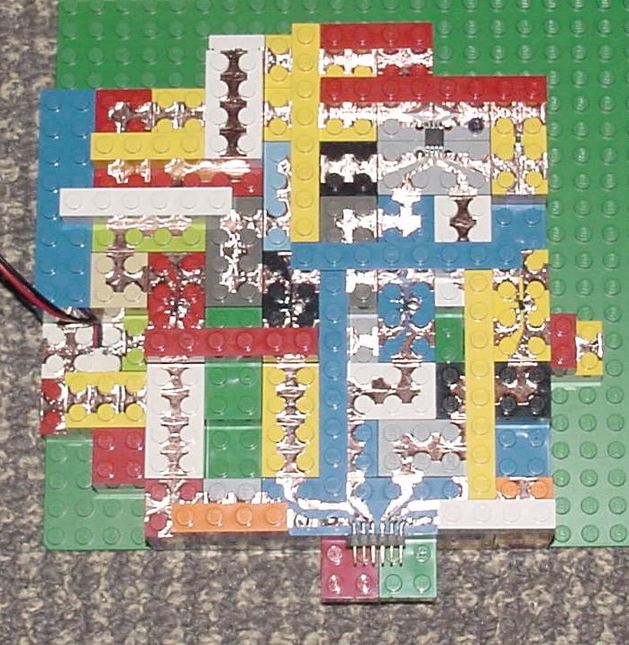
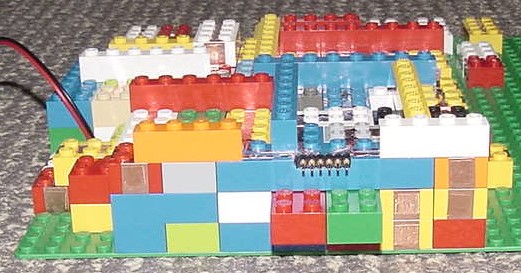
It is a 3d circuit. The lowest layer has ground and Vcc, then there is a layer of vias and insulators, then the main routing layer with most signals, and the fourth layer is used for one cross-over and further mechanical stability. Vertical connections through vias can occasionally exhibit contact problems, depending on how they are built. These can typically be fixed by applying pressure from the top. Horizontal connections are solid. In my first build I connected the MOSFETs wrong, which pulled some of the microcontroller inputs to ground, and made programming impossible. It took me a few hours to figure this out, because I thought there are contact problems with my programming cable. Once the MOSFETs were connected correctly it all worked beautifully and I could go to sleep at 3 am.
I then programmed in assembler full-step, half-step and microstepping of the stepper motor. The stepper motor I used is a $4 surplus item from Alltronics.com (They have quite a few cool things for unbelievable low prices. I bought a few steppers, solenoids and a linear bearing). It is a 17.5 Ohm unipolar stepper with 1.8 degree steps. The color coding of its cables was different then what Neil told us, but this was easy to figure out with a little multimeter (white and black are the center points and are connected to plus; white/brown/red is one set of coils and black/blue/yellow the other; for right turning they have to be energized brown/blue/red/yellow). I used the stepper to turn one of the discs in my final project (see further down for pictures). Everything worked great.
Assignment 9 - injection molding, shrinking Lego e-bricks
The stepper motor circuit was a pretty large structure in e-bricks. The circuit itself is still fairly small (one 8 pin microcontroller, 4 MOSFETs, voltage controller, capacitor, resistor and two sockets for power supply and stepper motor). To make this not just a prototype method, but get it closer to a production method, one has to shrink the e-bricks. Since Lego produces flat pieces (a third of the height) as well as smaller pieces down to one peg, I decided to use these flat pieces to shrink the circuits by 3 x 2 x 2 in volume. The 3 is the height and the 2 are in the lateral dimensions. I used every other gap between pegs as conduction lines. Now I am using each row of pegs as a conductor.
The application of the vinyl cut copper is now a lot harder, but still managable. The circuit above is not yet tested but should be the control for a solenoid (one MOSFET and microcontroller). I did two iterations on the copper foil shapes. I will need one more spin to remove the biggest problems. I tested all conductors with a multimeter. They are ok. In the next photo one can see a sheet of copper foil with several shapes cut out.
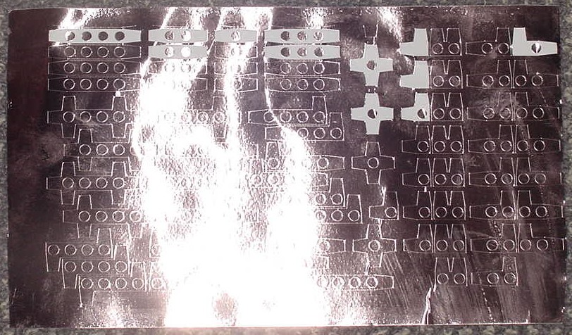
I used force 90 and speed 2 on the vinyl cutter. It would be better to use a bit thicker copper foil to bridge the gap of 0.2 mm which is built into the lego pieces. Also, one does not need the expensive copper foil with conductive adhesive. A non conductive adhesive would do just as good. The holes for the pegs are 5.3mm in diameter. The pegs themselve are 5mm in diameter. (some dxf files for various shapes: lego_small_1.dxf, lego_small_2.dxf, lego_small_3.dxf, lego_small_4.dxf, lego_small_5.dxf)
To make vertical connections more reliable one would ideally make the pegs conductive, too. Then the peg and the inside wall of the top lego piece would produce and nice contact which is formed by shearing motion, rather than just pressing two pieces of copper on top of each other.
The Project - Personal Fabricator
During the summer when I browsed through the Bits and Atoms webpages, I found an interesting idea for a low cost x-y position system called "Swinging Arms". The idea there was to replace expensive linear positioning with rotational positioning using two coupled arms each with one joint operated by two motors. I liked the thought, but somehow the whole thing looked pretty instable, particularly in z-direction. And so I started to think around and over and under this idea until I came up with what I think might be a novel thought for such a tool. Imagine a turntable, where the material that you want to machine is the record (it is mounted on the turning table) and where the machine head is the tone-arm. I generalized the tone arm to another turning disc, which could have several machine heads mounted on its circumference. So imagine two turning discs with their centers of rotation offset from each other. If the tool head (or the boundary of one disc) passes exactly through the center of the other disc, then this system can reach any point on the record, by turning both, the tool-disc and the sample-disc in appropriate fashion. Two turning discs seem much more stable than two swinging arms. Particularly the sample-disc would have great support, think about a lazy-susan type design, and also the tool-disc would not need to stand completely free, but could be supported wherever it does not overlap the sample-disc. How much easier can one make it than two turning discs? Each tool head would of course need some sort of z-control to move it into action and out of action.
One could perhaps use a Dremel tool as a milling/drilling tool head, maybe one of these low cost lasers for laser cutting and maybe a pen for plotting. A pick and place head would be a wonderful head as well. Then the tool could be expanded to do some assembly work.
Specs
- This desktop tool should cost less than $300 in components and materials. Time to manufacture and assembly are not part of the cost. I anticipate that initially one only distributes the design files for others to replicate this tool. Later one could sell a kit with all the components. Ultimately a manufactured tool could be offered.
- Tool envelope should be around 10" in x- and y-direction and 2" in z-direction. After all this is a desktop tool.
- Spatial resolution/precision should be 0.1 mm or better. Since one critical application of this tool is milling out PCBs, and we use a 0.38 mm milling bit, a resolution of 0.1 mm should be sufficient.
Some Facts about Cost
One can break up the personal fabricator into three main components: bearings, actuation and electronics.
Electronics
Electronics is the most straight forward. We can mill out our own PCBs. We have a very powerful microcontroller (ATMEL Tiny 13), which costs less than $1, and should be sufficient to control actuators and do any other user interface functions. Add to this a few other low cost components (resistors, capacitors, voltage controller, line drivers, ...) and we should be able to manufacture all our electronics for $20-$30.
Bearings
Typically such tools use linear bearings of various kind, ex. rods with bushings which can slide on the rods. Such components are fairly expensive and run in the $100-$300 range. I found online self-made solutions which could be built for about $30. They all use cheap 608 skate ballbearings and rods or pipes. Some of the problems with the self-built solutions are alignment and dealing with debrie and dirt. However, the skate ballbearings are a commodity product and one can find single units for $0.85. I purchased Delrin ABEC-3 (a spec indicating precision) ballbearings for $1 each. This is amazing, a wonderful ballbearing for a buck. And there is a wide range from $0.8 to a few dollars covering ceramic bearings and other special features. To base bearings in some form on these low cost commodity ballbearings makes absolute sense. I have not found anything better and cheaper.
However, instead of linear bearings I will go with my rotational turntable design. Because all I need to do, is to use two ballbearings for an axel which attaches to the turntable. I can't think of anything lower cost. Additionally, the dirt issue is absent, because there are no ballbearings openly rolling on a rod or other surface. Since only two ballbearings per axel are required, one could even afford higher quality bearings if there is a need for it.
The case of flexures. I like them very much. They have unique properties, and it is not too difficult to manufacture them. However, they suffer from some serious disadvantages. I cut a flexure which could provide almost 2" of motion, but which suffers unacceptably low stiffness in the z-direction (perpendicular to the sheet it was cut out). And 2" is not a particularly long range of motion. Scaling this up to say 6" would further erode stiffness in z-direction, and would also make manufacturability an issue. The best way to cut these flexures would be an EDM, but that is very expensive. One can fix the stiffness issue by using two, three or four identical flexures as seen in one of the photos above, but this increases cost of material, manufacturing and assembly. It might be the right solution for the z-elevator for my personal fabricator, but I am not so sure. Since I need only 2" of movement in the z-direction, I might be able to fix the stiffness problem with going to a thicker piece of Al.
If I stick to my turntable design, the total cost of bearings is almost negligible. Including cost of some structural components, I estimate that I will need less than $10 for the bearings in all 3 degrees of freedom.
Actuation
The typical actuation setup for a desktop milling tool is either a long screw (rod) which is turned by a stepper motor, or a capstan. A nut sitting on the screw moves up and down when the stepper turns the screw. The capstan solution is a wire which is running between two cylinders, one of which is turned by a stepper motor. The moving wire is attached to the piece which has to be actuated. The capstan is fairly cheap but less acurate, the screw and nut solution can be made precise, but is also more costly. Another question is stepper vs. DC motor. A stepper, screw and nut actuator could probably be made around $30-$50, depending on the quality of stepper motor and screws used.
Again, the turntable design opens some unique options. Since we need rotational actuation and not linear actuation, one could directly link a motor to the axel, no gears needed. The question is what kind of resolution can one achieve with this setup. As Fadi, a former student showed, windshield wiper motors are cheap commodity products which do the job. One could also use a big gear as the turntable and actuate the gear with a worm which is directly attached to a stepper motor. Since the worm/gear combination can provide a reduction of ~100 or more, one can easily achieve 0.1 mm spatial resolution. A capstan solution would also be possible, but with less reduction, perhaps more in the range of 20.
If a direct link of motor and turntable achieves 0.1 mm resolution, than this would be the cheapest and simplest way to go. We would not need any gears or worms and do not need to worry about backlash which is always an issue with gears. The main problem with a direct link seems to be torsional stiffness which translates to accuracy.
Another intriguing solution would be to build your own stepper motor into the turntable. Since the turntable is a big rotor, one could imagine to place some permanent magnets into the rotor and some coils under the rotor to turn the rotor in the same way a stepper motor functions. By placing coils and magnets intelligently, one could achieve a fairly high resolution. If the number of coils is N and the number of magnets is M (assuming they are evenly spaced around the turntable perimeter), and N and M have no common factor, than the number of steps for one full rotation is N*M. Using the half-step idea, where two coils produce a field at the same time, one can achieve 2*M*N steps. If we can place every centimeter a coil, choose N to be ~25, we could achieve 0.2 mm resolution. And since strong rare earth magnets are available at around $0.25-$1, it would in principle be possible to do that for around $15-$30. The electronics requires a bit more, because every coil of about 70-80 coils need to be switched individually. And I don't know if the achievable force is large enough for a milling tool. The fact that the force is generated at the perimeter results in a nice momentum. There would also be no coupling issues, since the rotor/turntable is directly actuated. This design hinges mainly on the availability of cheap and strong magnets.
Yet another solution is to use timing belts. These belts are quite cheap (starting at $3) and they would not cause any backlash problems. They would provide a reduction of ~20, similar to the capstan solution, but would not suffer any slipping problems that capstans can. I ordered two belts from McMaster to start testing.
Total Cost
If we add up the estimated costs, $10 for bearings, $25 for electronics and 2x$20 for the two motors (for the z-direction it depends on the tool if a motor is needed - a solenoid is sufficient for a pen or cutter), we get $75. Add to this material cost for some structural parts and hardware (bolts and nuts) it seems like $100 might be sufficient. Even if I made a 2x error in my estimates, I would be well below the $300 target.
Some Progress
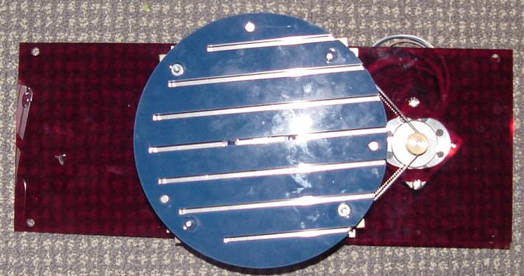
I discovered that the lazy susan in the galvanized version only costs $3.30 ($2.35 for 6 units). From a force and torque point of view, the lazy susan with an additional ballbearing for the axle is the best. I designed the base plate and how to fix the ballbearing to the disc. I made a disc where I strapped a timing belt around to function as gear (this was an idea from my friend Michael Adrian). The timing belt was 24" long. I made a circle with 194 mm diameter and scaled it by 0.995 (15 mill waterjet offset).
Cost of components so far
| item | price/item | total |
|---|
| lazy-susan | $3.30 | $6.60 |
| ballbearing | $1.00 | $2.00 |
| timing belt small | $2.52 | $5.04 |
| timing belt large | $2.77 | $5.54 |
| timing belt pulley | $7.49 | $14.98 |
| Total | | $34.16 |
More Progress
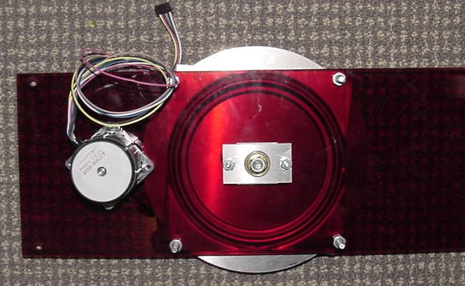
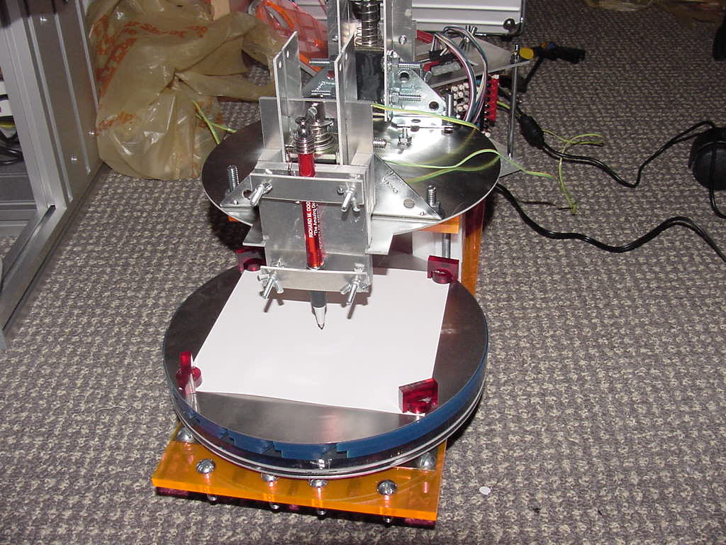
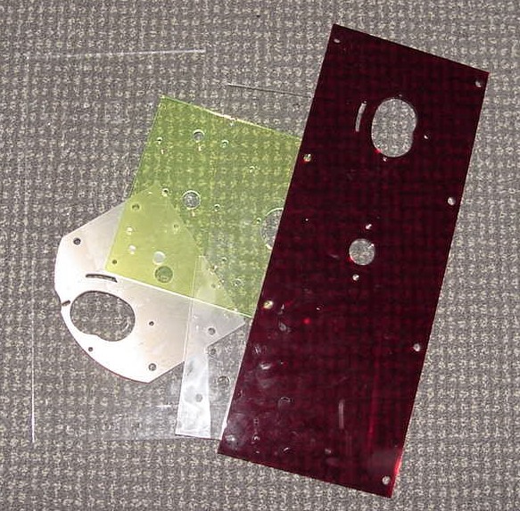
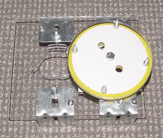
I did one iteration on the base plate to add holes to mount the stepper motor. I also built a T-slot table from three layers of acrylic cut with the lasercutter and bonded with acrylic cement (A liquid which etches the surface of the acrylic and produces a very strong bond. The major problem is that this is very very fast and it was a challenge to get everything coated and bonded before it dried out). The color of the acrylic I used is purely a function of what scrap material was available. The photos below show the disc assembled.
The next photo is quite a jump to the final machine. Well, not final, but as far as I got. It is functional. Both discs turn and one head can be actuated. Everything is controlled from a serial connection to my Apple laptop. The computer sends commands to the tool to instruct it how many steps each motor should be turned and in what direction, as well as for how long the pen should be lowered.
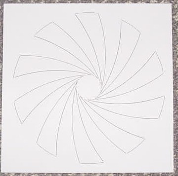
A nice drawing created with the machine above.
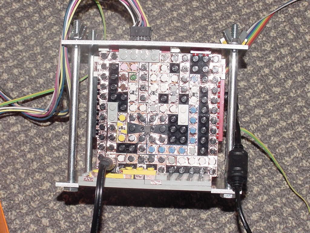
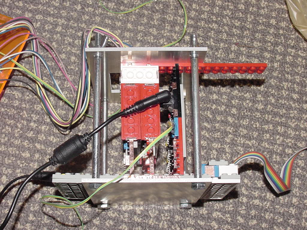
The electronics are entirely built from my lego circuit prototyping method. It consists of a backplane which holds the power supply (5V voltage controller and plugs for 9V AC adaptor. 9V is sufficient for stepper motors. Solenoid needs 24V and has separate power supply.) It also holds the plug for the serial connection as well as the 4.7V Zener diode and resistor to create one line serial connection for the computer to talk to the machine. Eventually this should be bidirectional serial connection. Perpendicular to the backplane are three boards. One for each stepper motor and one for the actuation of the solenoid. Each board has a Tiny13 which is connected with a one line serial communication to each other and the computer. It listens for commands to execute.
- 'axxx' turn base disc xxx steps to the right
- 'Axxx' turn base disc xxx steps to the left
- 'bxxx' turn tool disc xxx steps to the right
- 'Bxxx' turn tool disc xxx steps to the left
- 'zxxx' pen down for xxx 'time' (the way it is currently programmed, the 'time' depends on the on_count and off_count of the PWM; this has to be fixed but was not essential for a demo)
- 'nxxx' set on_count of solenoid to xxx
- 'fxxx' set off_count of solenoid to xxx
- 'sxxx' set slow pen down time. (By default s is 1. Making this larger moves the pen down slower.)
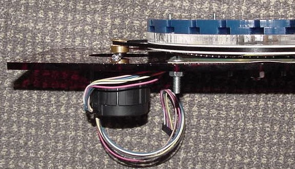
At the top we have the two cables for the stepper motors entering.
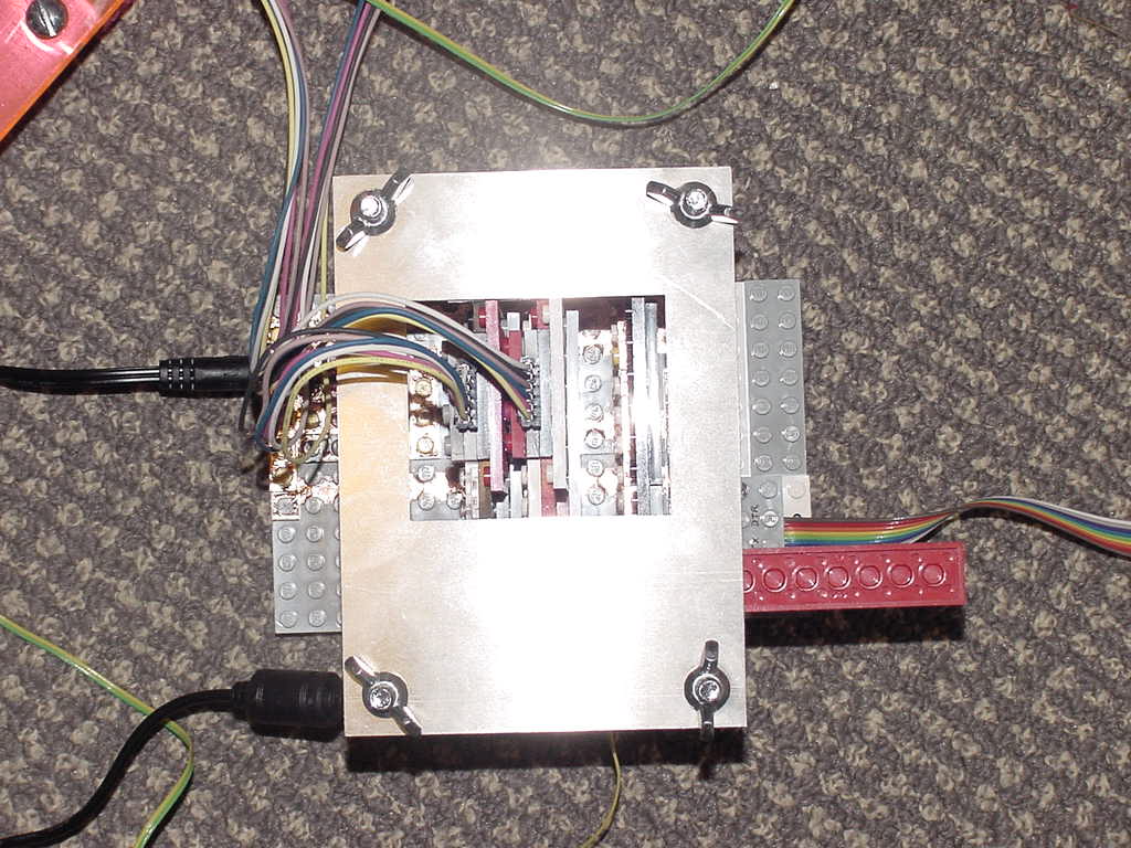
The following photo shows one of stepper motor controllers. It uses 4 MOSFETs to switch the various phases of the unipolar stepper motor. The aluminium cage with the wing nuts is to make sure that the boards are tightly connected to the backplane. Without it I had problems ensuring a good connection to all boards and contacts.
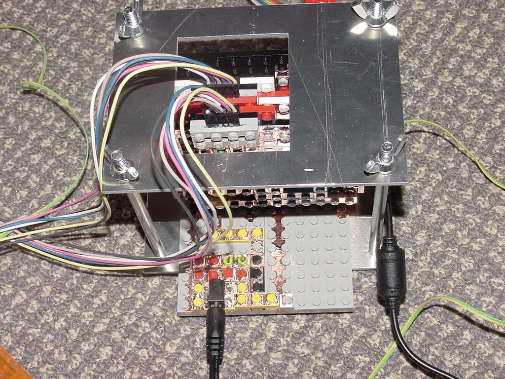
Here we see the 24V and the solenoid cable comming in from the side. The solenoid has a protection diode in parallel soldered directly to it. When the solenoid is turned off, the energy can be dumped out through this diode and protects the switching MOSFET. Before I had this diode I destroyed a few MOSFETs. I am using a 12.5A MOSFET to switch the solenoid. The resistance of the solenoid is 12 Ohm. At 24V this produces 2A of on current. Before that I tried two 1.6A MOSFETs in parallel but it kept killing the MOSFETs. I first thought the current was the problem, but now I think the lack of the protection diode was probably the reason. I use PWM to controll the force with which the solenoid is actuated. This force can be set through commands the computer sends (nxxx for the on_count in the PWM and fxxx for the off_count; ex. n010; default is n020 and f010).
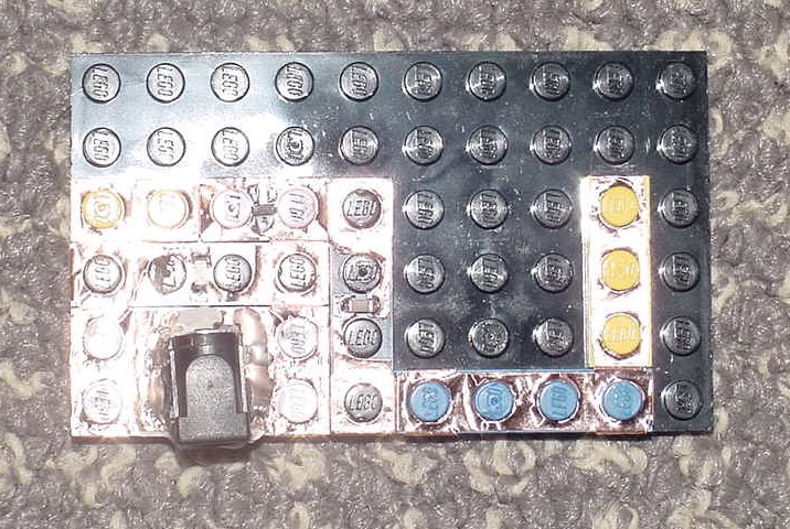
This is a power supply I used for programming the Tiny's. I removed one board from the backplane. Connected it to this power supply, connected it to a special lego programming cable. I used avrdude to write the new hex file, and then I plugged the board back into the backplane. You can see some hot melt glue to strain relieve the power plug.
Here are some iterations of base plates. It took me quite some trial and error to figure out where every hole has to go, and the design kept changing over time, too. The second picture shows a completely failed top tool disc. It rotated fine, but the mounting plate was too large and had no clearance for the tool heads to rotate.
Things to do
- change base plate to move discs further appart.
- make the small mounting plate for the tool disc setup from Al. This way it can be thinner which will allow me to move the timing belt pulley further down on the motor shaft.
- change tool disc into a modular design, where heads can be easily exchanged and adjusted so that they travel exactly throught the center of the lower disc. (currently this is not the case. This means that the center of the lower disc is unreachable for the tool)
- better linear bearings for solenoid actuated pen or knife
- milling head with stepper motor and DC motor to turn the tool.
- head for vinyl cutting knife
- voltage controller for 9V or 12V to eliminate the two external power supply of 9V and 24V. Everything could then be operated from 24V.
- make real PCBs for electronics. Lego is good but I am worried about the longevity of it.
- bidrectional communication with the computer
- maybe introduce a master processor (tiny13) to handle some of the calculations.
- use built in PWM feature for solenoid actuation, rather than the programmed one I am using right now. This then allows the solenoid board to actuate the head and while it is actuated, to listen for commands, say the pen-up command.
- adopt a file format and do all the necessary calculations to translate straight lines to the correct amount of steps for each disc.
- closed loop control of discs. Steppers can miss a step. Use a variable capacitor to measure where the disc is exactly located. I am not sure if this could be made acurate enough to achieve 0.1 mm resolution.
Lessons learned
My rotational bearing setup with preloaded lazy-susan and roller skate bearing turned out to be quite effective and very cheap. The main issue with this design is the following. If the tool head cannot be acurately positioned relative to the lower disc, any design would be scaled larger or smaller simply by changing the zero point. This is a big disadvantage compared to a linear x-y table. In the case of a linear x-y table, if the zero point is moved or incorrect, the design is simply translated. It is being cut out at a different position. The dimensions do not change. In case of the turntable design this is not the case. If the tool head is moved further to the perimeter of the base disc, the same amount of turn on the base disc produces longer lines than closer at the center. It is therefore crutial that the relative position of the tool to the base plate is very accurate. This could be accomplished with a closed loop control of the tool disc. As long as one knows the exact absolute position of the tool, computation can ensure that the dimensions of what is drawn or cut out do not change, even if the zero position is changed.
The turntable design also nicely allows a tool with multiple heads. It would be nice to create an open interface (mechanical, electrical and software) to allow others to design their own tool heads. This would further reduce price because only a new head would need to be built, rather than the whole machine.
Getting tools installed on Apple
Installing avrdude
This was quite a journey. First installed Mac OS X Xcode Tools Version 1.1. Instructions of what follows is available at http://www.mip.sdu.dk/~frodi/macosx.html Installed binutils-2.16, gcc-3.4.3 (had to add to Path /usr/local/bin with export PATH=$PATH:/usr/local/bin), avr-libc-1.2.5 and avrdude-5.0
Installing avra
With Manu's help I could install avra, the assembler for the AVR family of microcontrollers. I verified it with compiling hello.asm. It creates an identical hello.hex file.
USB to Serial/Parallel port
I have now two different USB to serial converters installed and running. One from IoGear, the other from Keyspan (serial/parallel/2USB). They can both work with the first hello program (read output from the tiny13).
Programming the tiny13 via the parallel interface
edit