i0 Trolley
Background
The Tech Model Railroad Club of MIT is credited with inventing one of the first real-time control systems in the 50's (you can read about their history here). In 2002, they replaced their huge
banks of telephone switches with a Linux PC and modern circuit boards with miniaturized relays and PIC microcontrollers. However, throughout this history, the control system has been a box "under the layout", that is to say, not part of
the train world, which precisely
controls the voltage across each pair of rails (there are hundreds, corresponding to different segments of track interfaced with switches and turntables) so that a train maintains a constant speed, even as it crosses between blocks, without shorting anything. With Internet 0, it's possible to always provide constant power across the rails, but send signals modulated on the power, setting up a bidirectional network between the trains and the control system, allowing all manner of feed-foward and feed-back control to occur in a microcontroller on board the train, instead of treating the train as a passive device between the rails. Many application scenarios, such as tracking the train's exact position in real time, making it follow a schedule, and using sonar to detect possible collisions, can be imagined.
Overview
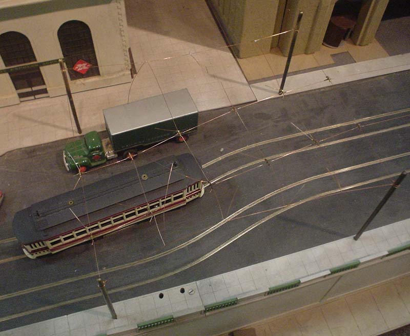
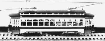
My project will be to show a proof-of-concept of this network on TMRC's trolley layout, which is separate from the historically relavant train layout, and currently has no control system besides a DC power supply. I'll purchase an HO-scale Brill trolley as shown at the top of the page, and add a circuit board in the trolley body (there's plenty of room) between the wire taps from the rails and the wire taps to the motor. At a high level, this circuit will be a node on the internet 0 network, and PWM the motor to control the trolley's speed. Then, I'll construct a control box which has the same i0 connection to the trolley's rails as the trolley, but connects to a three-wire i0 network as well, with a gateway to a master PC. Then, control commands, and if I'm lucky, feedback data, will flow along the rails between the trolley and the PC, as the trolley moves back and forth along the track.
Electrical operation
The method of communication (the i0 'click') will be a multi-megahertz wave, pulsed for a couple microseconds. It will be generated and detected by a resonant RLC circuit, forming a low-bandwidth band-pass filter on the receiving side, and a resonator on the transmitting side. Since the same circuit is used for both functions, either side can switch between transmit and receive mode. Thus, the requirements for an i0 network are met, and we get UDP functionality automatically; we use this to send data back and forth.
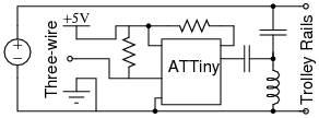
Controller schematic.
Mechanical operation
I will buy a Bowser Brill HO trolley (the type used at TMRC) to modify. Time permitting, I will laser-cut a simple transparent acrylic case to replace the scale model of the trolley exterior so that visitors can see the circuit operating inside the trolley.
Process of construction
I'll make all circuits using the Modela workflow, and may use the lasercutter to construct the case. My schedule for development depends largely on the order of operations to get the resonator working (we'll discuss) and the time of arrival of the trolley itself.