
Moving towards my final project I wanted to find an easy way to create regular dodecahedrons in which I could place electromagnets on each face. My first attempt was using the laser cutter and my second (uncompleted) attempt was meant for the 3D printer. Both models ended up with two, six sided halves of a dodecahedron which would be press fit together.
The laser cut model was meant to be simple and easy to assemble. It failed for two reasons: (1) there were way more parts than I realized and (2) the edge of a piece of acrylic cut by the laser cutter is not actually perpendicular to the face due to the heat of the cutting procedure and the focus of the laser. For small pieces reason 2 becomes a serious issue.
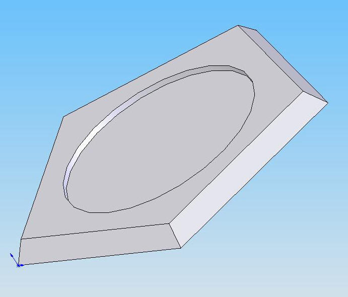
Here is one of the 12 faces composing the shape.
There are two kinds of joints which hold faces together: (1) permanent fit which are glued and, (2) press-fit on one side and glued on the other.

The permanent side is meant to press into the rectangular slots on the faces and reinforce the desired angle between faces with the larger planar surfaces. Issues arose when the inconsistent cutting width of the laser combined with the small size of the part. the faces were no longer perpendicular thus they could no longer be used to reliably guide the shape of the structure.
The second joint type is meant to be permanently attached on one end and snap in and out on the other end.

This is a close shot of a permanent joint joining two faces.

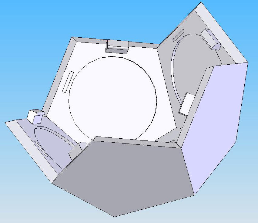
The two halves fully assembled can be seen here. Notice that the unconnected halves have the press fit joints in alternating slots. The other joints are glued in place using acrylic glue. The corner of each joint closest to the center of each face actually define a circle (intended) in which an electromagnet could be accurately placed.

And... here are the two sides press-fit together. The actual construction process ended up being about 3-4 hours which could be shortened with experience but would always be too long due to large number of parts in the construction.
The next strategy attempted to solve this problem by printing two halves on the 3D printer. Though the printing process would be long, the man-hours would, hopefully, be significantly reduced.
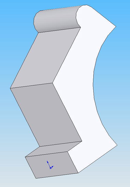
In the Solidworks model each side was still composed of 6 faces separately modeled though the final 3D model would combine these faces into a solid shape.
One of these faces (per side) is used to join the other 5 faces.

The other 5 faces have a tab/groove press-fit model which allows them to be pushed together.
Here is one side of the assembly.
Unfortunately an almost permanently broken 3D printer prohibited me from ever realizing this model.