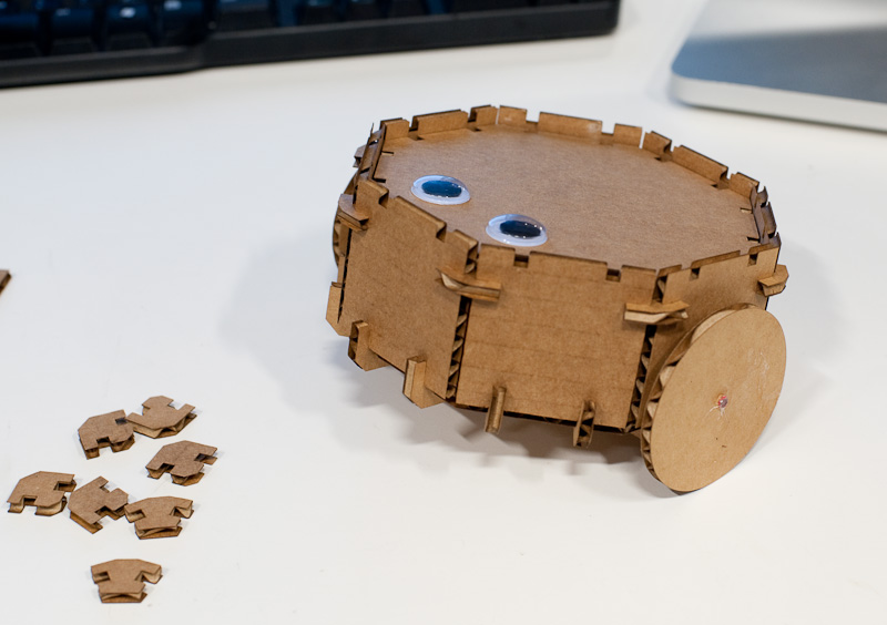
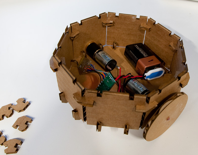
Cardbot is a functional robot made from laser-cut corrugated cardboard. It is battery powered and wirelessly controlled over 802.15.4 (Zigbee.)
For this project, I wanted to do something more than just a set of building blocks like GIK, but I wasn't sure what. I had some ideas for some custom storage containers that all ended up being variations on the cardboard box—not very exciting either. Then I had the idea that I could build a kit for a robotic base, itself a press-fit assembly kit, that could also serve as a mobile base for other press-fit constructions.
My plan was to build the robot and then cut a bunch of generic building blocks that could go on top of it, but working out the details of the robot ended up taking enough time and I didn't want to take too much time on the laser. It should work with other parts cut from the same thickness of cardboard, though.
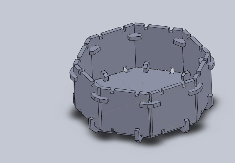
I designed Cardbot using SolidWorks, which enabled me to visualize how the pieces fit together before I actually cut them. It also enabled me to parameterize the sizes of the pieces and the widths of the slots where they fit together, (which ended up being important later.)
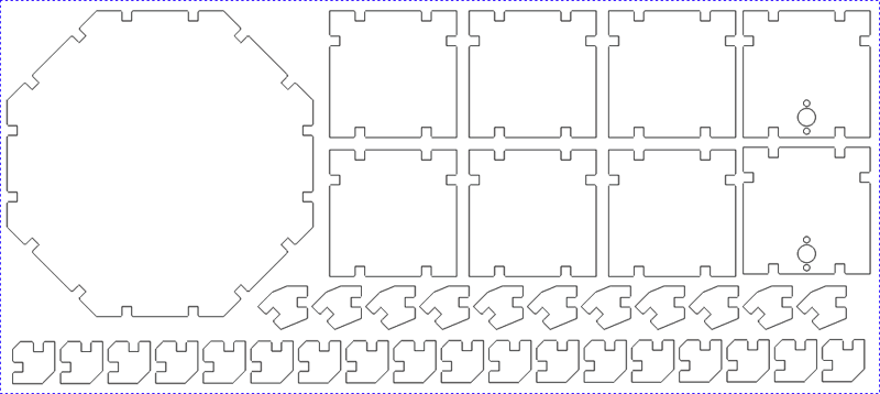
To get the 2D vector files to cut on the laser, I created a new SolidWorks drawing at 1:1 scale and pasted in projections of my parts. I then opened the resulting file in Corel Draw to adjust the line widths so that the cutter would recognize them as vector objects and to actually send the file to the cutter.
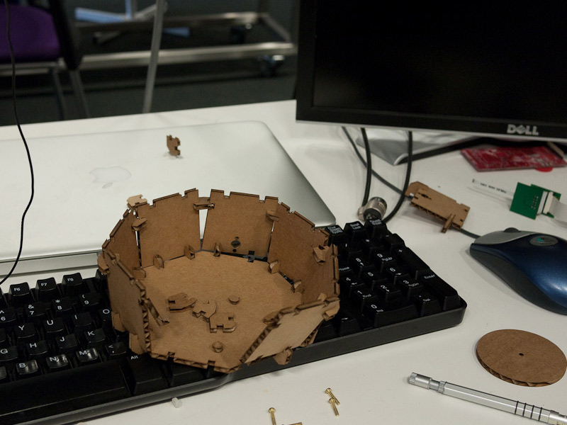
I cut the pieces on the Universal laser in the CBA shop. I used the 2.0" lens, at about 70% power, 15% speed, and 120 pulses-per-inch. It didn't flame up when I cut, and the edges were very clean and cut all the way through.
I ran into a few problems the first few times I tried. The first time I cut pieces, I discovered that I had accidentally set my SolidWorks drawing to 2:1 scale, so my pieces came out twice as big as they were supposed to be. It was hard to see on the screen, but was immediately obvious when the laser started cutting slots that were way too wide!
After scaling everything down to its proper size, I got a complete set of parts. I tried putting them together, but discovered that I didn't account for the beam kerf enough, and they fit together too loosely.
My original design was for slots 4mm wide, cut on the center of the line. I adjusted my drawings for 3.8mm wide instead, which worked perfectly. The pieces fit together snugly, but were not difficult to fit together.
In order to finish the design as a working robot, I added a pair of motors, a microcontroller and radio board, and a motor controller board.
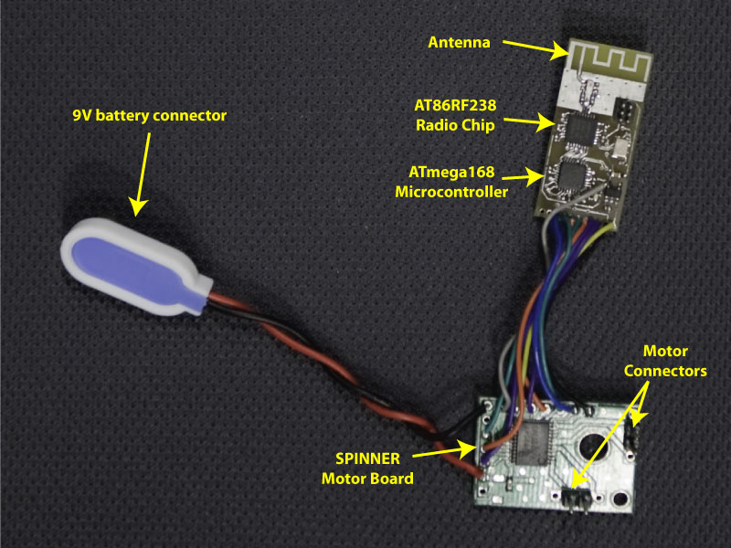
The microcontroller and radio board is one of my previous designs. It uses an ATmega168 as the microcontroller, and an AT86RF230 single-chip 802.15.4 radio. Both chips are QFN32 parts, so the board is very small. To keep costs as low as possible, I integrated an antenna into the PCB itself, based on a TI application note. The antenna design is for 31 mil FR4 and I used 62 mil, but it still works well enough. The boards were commercially fabricated, but I did all of the stuffing and assembly myself.
The motor control board was borrowed from a SPINNER unit. It is basically a breakout board for the TB6612 dual motor driver chip. For each motor, the chip takes a two-bit direction input (forward, backward, brake, or coast) and a torque input in the form of a PWM signal. These are generated by the microcontroller on the radio board and provide 256 levels of torque control in both directions.
The system is powered from a 9V battery. The supply is regulated to 3.3V for the digital logic, and the full 9V is used to drive the motors.
The firmware for the ATmega168 is written in C with avr-libc and compiled with avr-gcc. I used Atmel's AT86RF230 Transciever Access Toolkit (TAT) as a starting point for the radio code. The TAT is part of the AT86RF230 Software Programmer's Guide, available on this page.
The software is a Python script that runs on a PC and uses Pygame to read commands from a joystick and send them to the robot using another Zigbee board connected to the USB port.