This week, I tried to make flexible membrane buttons, like the kind you'd find on a TV remote control. The buttons are constructed so that they can be deformed, bringing a part of the membrane with conductive or resistive material on it into contact with a pair of pads on the PCB below. A microcontroller can detect this contact and interpret it as a button press.
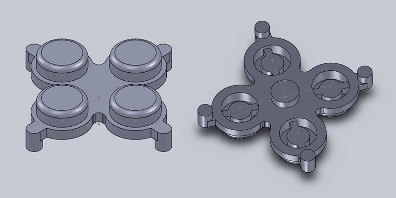
To accomplish this, I needed to make a two-part mold, since the buttons need to be at least partially hollow, with a raised area that only contacts the surface below when pressure is applied to the button. I started by drawing the positive shape in SolidWorks:
As I was drawing the part, I made sure to draw it so that the negative mold would be machineable. All of the outside corners on the part (which are inside corners on the mold) are at least the tool radius. Everything except for one feature on the inside of the buttons is millable with an 1/8"" square endmill; that one feature requires a 1/16" square endmill.
Then, I created two rectangular extrusions to serve as the top and bottom parts of the mold, and subtracted my positive model from the two halves:
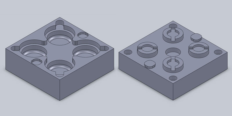
On the top part of the mold (to the right of the above image) the hole in the middle is for the material to enter, and the four holes around the outside are vents. The material left on the piece can be trimmed down, but some can be left to help align and fasten the membrane to the PCB. The holes don't go all the way through in the model so that they don't have to get milled all the way through; I drilled through the depressions on the drill press after I finished milling the mold.
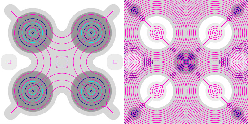
I used the fab modules to generate my toolpaths. I ran into a few minor issues that I had to work around. First, SolidWorks starts its headers for binary STL files with the ASCII text "solid" in the 80-byte header. I'm not sure why it does this. It confuses the fab modules into thinking that it's an ASCII STL, and the modules print an error to that effect and exit. I changed the first byte of the file to something other than 's' with a hex editor so that the fab modules would accept my STL files.
Second, SolidWorks uses a weird convention for its axes. It considers the XY plane to be the front plane, and the XZ plane to be the top plane. That means that if the parts are drawn with the features on the top face, when sliced along the Z-axis, the parts will come out sideways. stl_path doesn't have an option to slice along a different axis, but stl_png will generate images on any axis, so I used stl_png to produce the PNG images, and then png_path to produce the toolpaths.
Since I needed the two halves of my mold to mate together perfectly, I wanted a smooth surface to mill into on the wax. One piece of wax I used originally had some other failed designs milled into the surface. John D. showed me how to use the Bridgeport mill and I used a large endmill to quickly face the block so I could re-use it. Then, after putting it in the Modela, I generated a facing toolpath from a solid-gray PNG, taking off about another millimeter to ensure that I had a smooth surface parallel to the bed of the machine.
The Modela was actually reasonably fast with my toolpaths. The rough cut for the bottom mold (top surface of the buttons) only took a few minutes. I also cut a finishing path on the bottom mold to better round off the fillets on the edges of the buttons, with 0.1mm steps. Since the path wasn't actually removing any material until it hit the fillets, I manually edited the path file and removed the first few millimeters of passes to speed things up.
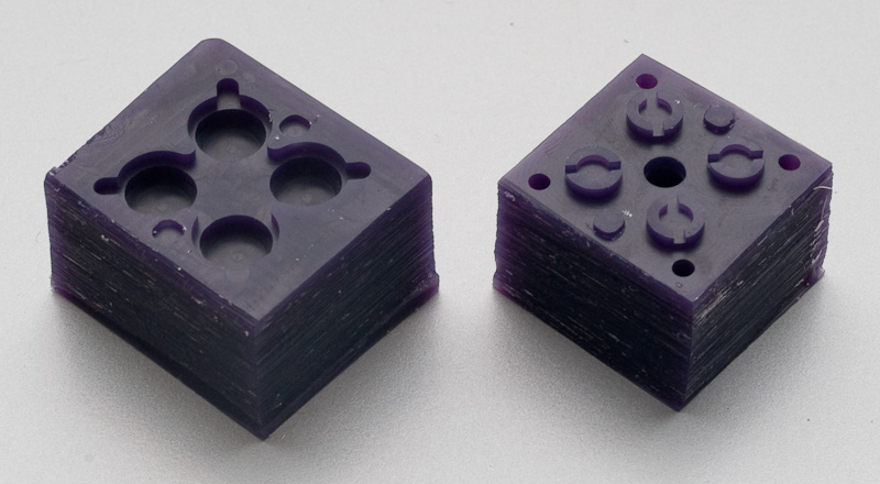
I cut the top half of the mold with a 1/16" endmill. It took about ten minutes and a finishing pass wasn't necessary.
I cut the two pieces of the mold apart with a hacksaw. The machineable wax cuts really easily. The alignment features that I designed into the mold to line up the top and bottom parts fit very snugly, but perfectly lined up the two halves.
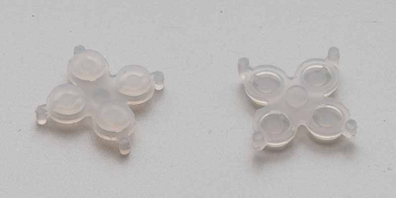
I used my mold to cast my part in Dragon Skin 10 Fast. Since the material was fairly viscous after I mixed it, I used a syringe to force it into the fill hole in my mold until excess material bubbled out through all four vents.
It only took about an hour for the Dragon Skin to cure at room temperature. Demolding went perfectly and the parts easily came out of the mold. The material in the long vent and fill holes even pulled out cleanly. There was a little bit of flashing around the mold line, but that was easily cleaned up with an exacto knife.
I didn't have a chance this week to make a PCB for my buttons (there don't appear to be any 1/64" endmills in the CBA shop anyway) so that's the next thing to try. The buttons are much squishier than the kind one normally finds on remote controls (due to choice of material) so they could be interesting if I could make them pressure-sensitive, instead of just binary on/off switches.