Creating a Mold
For this week's assignment I had to make a mold and cast an object from it. I decided to create the Terran emblem from StarCraft 2 so that on those rare nights where I have time to play, I can gaze fondly onto the token as I get owned by people who are better than me.
Step 1: Designing the File
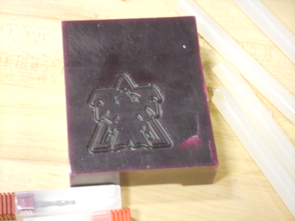
I was lucky enough to have an image to look at while I designed my file - although the next step in CAD growth is going to be learning to create documents purely from imagination. Here is the image I started with:

The design process went a little something like this:
- Pick an endpoint along the trace of your symbol.
- In Illustrator, use the line tool to draw a line along the trace of your symbol. Take note of length and angle
- In Rhino, draw a line with the same length and angle using the "line" command.
- Continue steps 2 and 3 along the trace using the lines and angles method until you get to a curve.
- If you get to a curve, draw a whole series of lines connecting one endpoint to various points on the curve. The ends of these lines need to be able to "recreate" the curve.
- Use the "line" command again in Rhino to create all of the lines that make up the curve.
- Use the "point" command in Rhino to draw a point at the end of each line.
- Use the "Curve through Points" tool in Rhino and select all of the points you want on your curve.
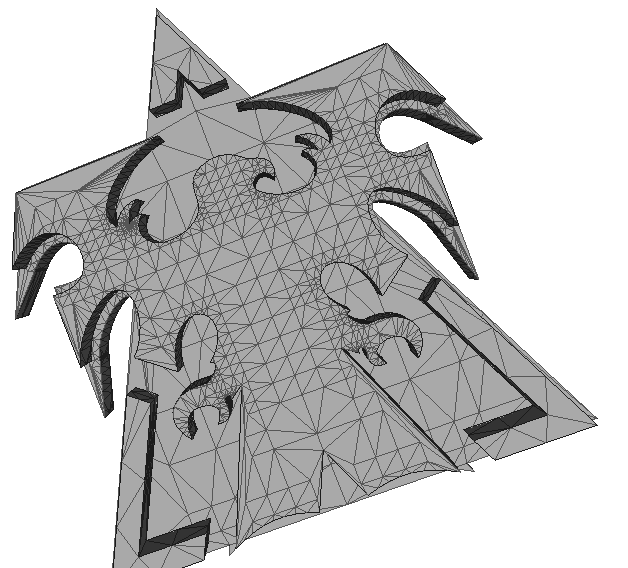
After following those steps for about 3 hours I managed to recreate the eagle and the surrounding triangles! From there I used the "Join" command to turn the dozens of separated lines into one continuous one, and then I made surfaces and "extruded" them.
I think the end result ended up being pretty nice! Below is version 1 -- I noticed the eagle was backwards and that the tail stuck out on the bottom, and corrected both issues for the final version.
Step 2: Milling the Mold
I decided to mill this thing on the Modella despite the fact that everyone told me that it was slower. The reason for this was simply that the Modella was available! I milled the image on wax, and learned a few things along the way:
- If you are using the fab modules, you want your "number of traces" to be set to -1. This is because each path layer assumes that all above material has been removed! In other words, if the top of your mold has a smaller area than the bottom and you don't mill out ALL unused area, you will cause the bit to slam straight down into the wax because the paths assume the wax has been removed!
- Speeds of 10 work just fine when you aren't milling circuit boards. The larger bits are far less fragile when cutting a material like wax.
- When printing a negative mold your top layer should NOT be the surface of your material. You are going to need the molded mold to have material on top of your "highest point" if you want it to actually surround it.
Here is a test (i.e. incorrect) cut:
I quickly learned that the above attempt at cutting would not yield a usable mold because it wasn't lowered into the material (i.e. I would have had to build a box around it if I wanted it to work).
Step 3: Casting
I am not a scientist. In fact, thanks to AP credit, I unintentionally graduated from Carnegie Mellon without taking a science course. This is probably why I had such a hard time with casting.
Apparently it is unwise to try to measure out a 1:1 ratio by eye... More specifically, it is REALLY unwise to try to measure out a 1:1 ratio by eye using only one cup. That's what I did! That is also why the plastic which should have taken 2 minutes to set ruined my first rubber mold.
Because I didn't get the "A" and "B" proportions correct, my plastic never set. I gave a second try using two cups which I could visibly see lined up properly, and used that to hopefully salvage the mold (in addition to creating a second rubber mold). I'll see how successful that was tomorrow morning.