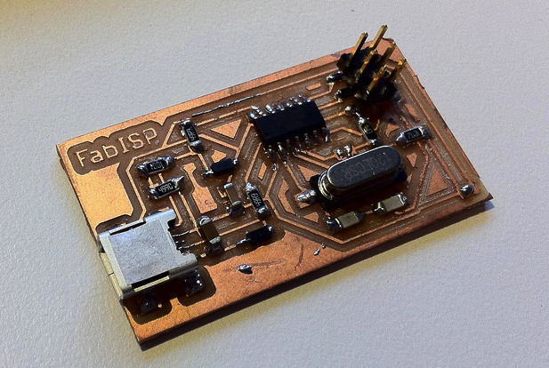
This week the design part of the normal workflow was missing since everyone got the same final goal for the next class: assemble the FabISP circuit. The ISP circuit is a circuit that can program microcontrollers (from the Atmel family). It is a very simple circuit, consisting only of passive parts, a Quartz (to control the timing for the microcontroller) and an Attiny (Atmel MCU).
We were left off, where the design process ended: normally when someone designs a circuit (I would recommend Eagle, because it's free or cheap and quite nice) the output can be exported as a black and white PNG. Normally the white part symbolizes the copper part and the black part where the PCB should be insulating. There are numerous ways to get a working PCB.
- Etching . a chemical process that is nasty, slow and produces a lot of excess waste. But this is the one that is the most accessible around a household
- Milling . a quite simple and fast way to make a PCB. A milling machine basically grinds off the copper from the raw PCB. The Mantis Machine makes this method very accessible. Fabable < 100USD.
- Vinyl cutting . extremely elegant but tedious job. If you master this method you are golden but until then it can be a very annoying workflow. Basically you cut your copper layer out from a sticky copper sheet (sounds simple, huh?). And then you can just stick it on to anything (wow, flex circuits).
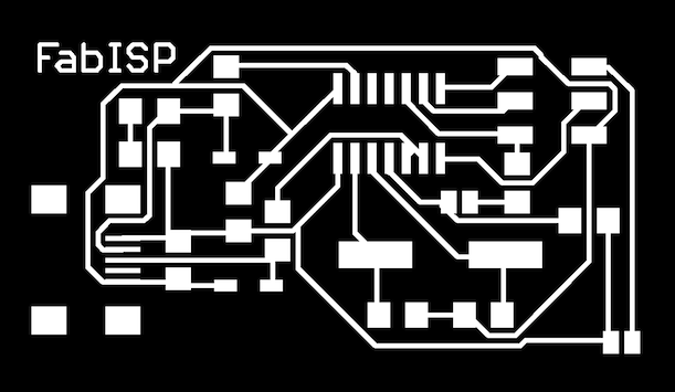
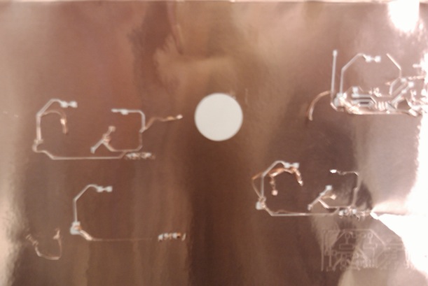
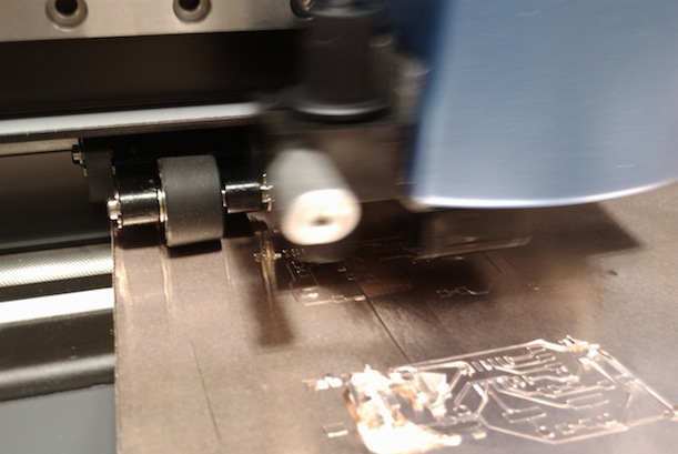
On the first picture you can see the original circuit design. I choose the most elegant method first: vinyl cutting the circuit. I failed many times before I gave up, here are my notes for future experiments. You have to figure out three things to get it working: the vynil cutter speed, force and the method of peeling it off. The first to parameters are functions of the machine you are using and a bit of the conditions of that day, but in general you should be able to get it right if you iterate well. For me at the end a velocity of 0.3 cm/s and a force of 45% worked well on the vinyl cutter in the basement of the Fab Lab at MIT.
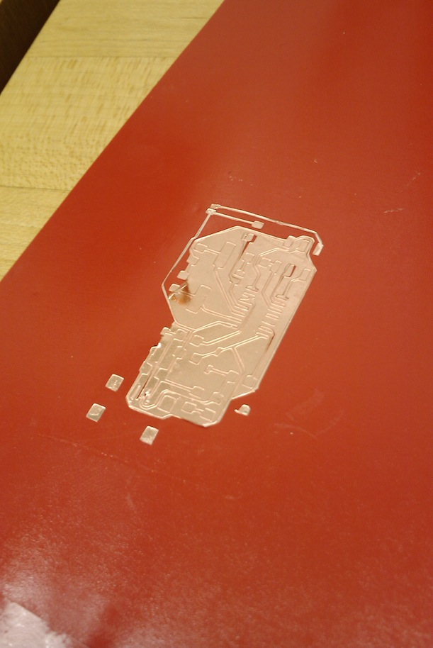
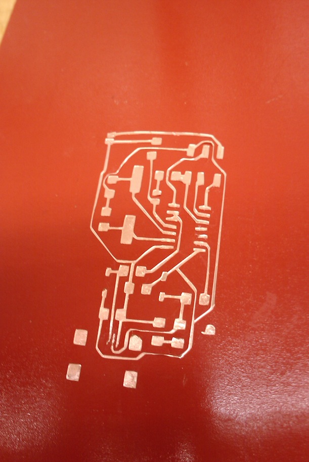
So assume you have the settings right and your copper layer is ready to be applied to the surface you want to have your circuit on. Great. Now you have want to get a piece of tape that will transfer your circuit from the copper sheet to the surface. You can either get all the copper to the new surface and than peel the remainders from the new surface OR you can do the peeling on the transfer tape and then stick only the important copper on to the new surface. I tried both and failed miserably. Multiple times :(. Pictures tell the story.
