Etching is a very quick process to make PCBs and my preference. It allows you to make boards larger than what you can do with the modella, it allows you to use materials that you can’t mill (FB4) and it’s also much quicker. The total process time to etch a double sided board on 9″ x 6″ of FB4 is less than 30 minutes.
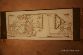
To start, clean the copper board. Wearing gloves, take acetone and a brillo pad to rough up the copper plate on both sides. This is done to take off the layer of copper that has slightly oxidized. You’ll see a color difference when you do this. Make the entire board on both sides look like the ‘new’ copper. Any areas that have oxidation will cause problems so be thorough. While scrubbing, rinse off the “gunk” using more acetone. When the board looks clean, rinse the entire plate with acetone on both sides. Run under water to rinse off acetone.

Next, take dish soap and scrub both sides. You can do this by applying the soap directly to both sides and rub in with your gloves. This will get rid of any oil on the board. Rinse it well with water. Do this step twice to remove any oil. Rinse under water again to remove any trace of soap.
Finally, rinse the entire board with isopropyl alcohol. The alcohol will take away any remaining residue left over from the previous chemicals. When both sides are rinsed with alcohol, run the entire board under water to remove the alcohol.
At this point, it is crucial that nothing touches the board where the transfer is to be made. Prop the board up against something to let it dry. Be sure nothing touches either face.
You should have a schematic in Eagle created. You can export the top and bottom layers of your circuit as a monotone png with 1200dpi. Next, open both the front and back circuits in photoshop as separate layers in the same file. Invert both layers so that the traces of the circuit are black. Mirror the top layer only. Using photoshop, this can be done using Transform>Flip Vertically.
Move the top layer, so that it lines up with the bottom layer manually. Once this is done, add three registration holes to an area on the board that has no traces near it on both sides. Hide the bottom layer, and print the top circuit on a piece of paper. Now hide the top layer and print the bottom circuit layer on another piece of paper. When both sheets are printed, overlay them and hold them up to the light so you can be sure that everything is printing appropriately and that everything is lined up. It is possible I messed up a step here, but the gist is simple. When you transfer the paper to the copper board, it will need to be mirrored. The one on the back side does not need to be mirrored, since it’s on a side that is already mirrored in itself. Make sure alignment holes are matching up.
When everything is good, print on to the transfer paper in the highest resolution the printer will print. This should be >1000dpi to get better ink coverage. Also, you must use a printer that has toner, since it’s made of plastic. This plastic will protect the copper board from reacting with the chemicals later.
This is simple. On both transfer sheets, cut out the holes with an exacto knife. Now tape down the top circuit so it can’t move.
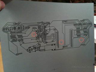
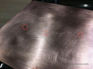
With a drill press, drill holes through the board where the registration holes are located. This will allow you to line up the holes on the other side of the board.
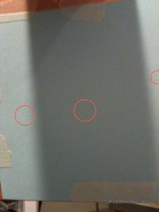
Now position the back circuit transfer with the holes. Tape both down. When you’re done, you should be able to see straight through the board where the holes are, ensuring proper alignment.
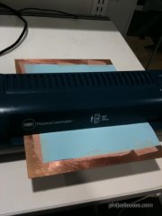
The laminator is a crucial step. It’s preferred over a manual method such as ironing due to it’s even speed and pressure. By hand ironing, it can mess things up quickly (see some improper transfer photos). Run the board through the laminator 4-6 times, melting the toner on to the copper board. When you’re done, immediately place the board in to a sheet of water. It should make a sizzle noise as the hot copper board rapidly cools. Do not touch the sheet until the paper dissolves. This should happen in about 10 minutes. You should notice bubbles have formed in the paper.
Get with a TA to help you set up the etching station. You should have etching solution, an air pump, and clips to hang your board. Preheat the solution and start the air bubbles. Note: You can also tape off parts of the board that have no circuit on it, reducing the amount of solution needed to etch your board. I used packing tape, but anything that keeps the solution off the board will work. Dip the board in the etching solution. Watch closely. In a few minutes, you should see the copper dissolve. To ensure both sides dissolve at the same time, once one side completes the reaction, you can flip pull the board out and flip it over. Chances are one side was getting more bubbles than the other.
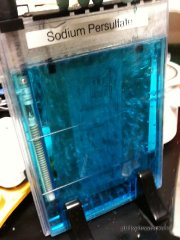
Bubbles decrease the reaction time by wicking away solution that has already reacted. As soon as both sides are dissolved, remove it from the solution and rinse with water.
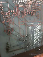
Put the solution back in the original container. It can not be thrown down the drain since it’s a biohazard. To finish the board, all you have to do is connect both sides electrically. To do this quickly, take very fine wire and strip it. Sew the wire through every hole on your board. Solder both sides of the wire in place using as little solder as possible. Then clip the wire as close as possible using wire cutters. Finally, add a bit of flux to each spot and touch it up with the iron. This will smooth out the via.
Psychophysiological insomnia (PI) is a very specific type of insomnia, categorized by excessive worrying about sleep. Its prevalence is unknown, but is frequently a symptom of Attention Deficit/Hyperactivity Disorder (ADHD), a common mental disorder, affecting 4.1% of adults, ages 18-44, in a given year. PI can be triggered by existing anxiety caused by life events. These events can range from a small task scheduled for the following day, to a major change months away. At night, stress from these events evolve into anxiety about not sleeping, making it more difficult for an individual to fall asleep, causing even more anxiety. This process repeats itself several times, until the individual’s exhaustion outweighs their anxiety, and the person falls asleep. This lengthy process deprives the individual of needed sleep and cognitive ability the following morning.
At night, the average person sets an alarm clock by determining an ideal wakeup time the following morning. To calculate this time, an individual thinks specifically about the following days events, and often the very tasks that cause stress. For example, if an individual has an interview the following morning, they would run through a series of questions in their brain to figure out what time to set the alarm. Variables in this mental equation are filled in by asking and answering questions. How far away is the interview location? What transportation mode will be used? Will there be traffic? What will the weather be like? How long does it take to prepare in the morning? What will be eaten? When is the best time to arrive? Should there be a buffer included in case of unseen events? These questions can quickly transform into anxiety about the interview, and before long, a new round of PI.
For those with ADHD, one major hurdle to following through with a routine is lack of motivation. If a treatment method is too difficult or the individual is unmotivated, the approach will often fail. Ease of use is always an important consideration in any design, but when designing a clock used by those easily frustrated, ease of use becomes paramount. Any frustration or difficulty may be enough to overwhelm the user and make them discontinue use. With Cognizant Clock, all that is needed from the user to operate is an up to date daily schedule stored online.
At night, to set a traditional alarm, a user is required to run through a series of questions in their brain to figure out what time to set the alarm. Frequently, this leads to anxiety, as the line of questioning needed to determine the correct wakeup time, is unfortunately the same line of questioning that is detrimental to restful sleep. Cognizant Clock tries to fade in to the background, relying on a suite of sensors and learned gestures to operate. In ideal conditions, the clock is able to operate without any human interaction for long periods of time. The user will go about their business and the clock, taking cues from the user’s schedule, will do what’s expected, when it’s expected.
Much of Cognizant Clock’s power comes from sensors that relay information back to a processor within the clock body. The sensors in the alarm chassis include a camera and an ambient light sensor. The camera will be used to silence and shut off the alarm and the ambient light sensor will be used to adjust brightness of the display.
Cognizant Clock uses advanced image processing to learn the user’s routine. Initially, as the user goes about his nightly routine, the Cognizant Clock will be in learning mode, analyzing data collected from all sources. Cognizant Clock is interested in two things. What time do you go to bed and what does the user look like when they get in the bed? After an initial period of time, the clock can be switched to “Live Mode.” It’s during this time that the clock is fully autonomous. After learning the ‘gesture’ of the user getting into bed, the Cognizant Clock will be able to automatically set itself, shut itself off in the morning and reset automatically if the user doesn’t get out of bed.
Cognizant Clock can set itself autonomously, by asking the same stressful questions the user would to determine the ideal wakeup time. It culls appointment times and locations from the user’s Exchange server or Google calendar, current and predicted weather from the Weather Channel’s application programming interface (API), current and predicted traffic patterns from TomTom’s award winning traffic database and newly released API. Cognizant Clock knows it’s location and can therefore accurately set the alarm based on all these factors.
When first awaken, people take a few seconds to gain their composure. A standard knee-jerk reaction is to silence the alarm as quick as possible by flailing your arms towards the snooze button. With Cognizant Clock, this is as simple as getting out of bed. The camera will watch for movement and will temporarily silence itself at the first sign of significant motion. To permanently silence the alarm, all a user has to do is get out of bed. The vision processing will watch a user get out of bed. When the vision system recognizes a person getting out of bed, it means the clock has determined the user is up and awake and keep quiet until the following morning.
If, however, the user silences the Cognizant Clock by moving initially, but does not begin his routine and falls back asleep, the algorithm inside the clock’s brain will recognize the user has not gotten up and will reset the alarm immediately.
A common annoyance among all people, not just those with ADHD, is waking up in the middle of the night only to look at the clock and realize they only have a few more moments to sleep. With Cognizant Clock, the concept of time is abstracted at night. By knowing the current time and the ambient light sensor to monitor room light levels, Cognizant Clock will only display a red or green light in lieu of the time. This will prevent anxiety if the user happens to awake in the middle of the night. If the current time is significantly before the calculated alarm, the clock will display a green light, signifying there is enough time to fall back asleep. However, if the current time starts to approach the alarm time, the clock will display a red light, signaling the alarm will go off soon and it would be in the user’s best interest to get up while they are already awake.
A lot of the clock’s functionality relies on connectivity, both to the internet and to the other sensors around the house. In order to build trust in a device that will be responsible for a user’s punctuality, the device must be robust and compatible.
Within the chassis of the clock is an 802.11g wireless networking card, able to join the most popular networks today. This allows to clock to pull real time data needed to make accurate functioning decisions from their sources online. In the event that an internet connection is lost, either due to a router error or an interruption in from the internet service provider (ISP), the Cognizant Clock can create a peer-to-peer network among sensors to continue functioning. When a change is made to a schedule while there is no network connectivity, the Cognizant Clock can pull the most up to date schedule from an offline source, such as a mobile phone or desktop computer. Using the Wake-on-LAN networking standard, a sleeping computer can be woken up and queried for the missing information. Wake-on-LAN is a networking standard that allows computers to be turned on after receiving a wireless signal. This is helpful in cases where desktop computers are off or sleeping.
Occasionally, the clock may need to behave traditionally, such as if a guest is visiting and needs to sleep in a room with the Cognizant Clock. In this scenario, the web application can be accessed, allowing the guest to set a static wake up time. When the clock functions in this mode, it can be turned off simply by touching the conductive metal chassis.
In the event of a power failure, the Cognizant Clock has a backup battery, able to function in a low power mode for over two days. While in the low power mode, the display will only illuminate while the conductive chassis is being touched. This prevents the battery from wearing down unnecessarily while still providing the necessary information, in a slightly less convenient manner.
Can monitor traffic and weather to update your ideal wake up time based on real time conditions. If there’s an accident, it will wake you up earlier.
If there is a snow storm, you may need an extra 30 minutes to shovel out your car/drive way and to heat up your car to melt the ice. This can be calculated while you’re sleeping and the wakeup time adjusted.
There is a meeting tomorrow but you don’t know what time it’s scheduled for when you want to go to sleep, because they haven’t settled on it yet. This features allows others to add an event to your calendar, or read new events from your existing calendar, that will wake you up, so you can go to sleep when you’d like and not have to wait on others.
Aesthetics:
Display:
Electronics
Milling vs Casting: Which is cheaper and what does the finishes look like?
Price vs Performance: Beagleboard or Gumstix Overo?
Gumstix Overo ($229) + Aluminum Case 12″x12″x2″ ($102) + Glass 12″x12″x.125″ ($9.35) + 4 x 7 segment displays ($17) = $459.35 funded from my own pocket and my group
]]>- Unknown
This week was networking. I created one segment of my clock and milled a board that would allow through hole components to be attached. It was quite simple with the arduino software on both ATMegas.
Set the pins to be in and out, then just send data across the wires telling one mc to turn on the segments of the display.
]]>- Wikipedia
Composites are created by combining two materials together to create a third hybrid material. The basic idea is to take two materials that complement each other, one strong and brittle material could be mixed with a weaker more flexible material, to create a material that is both strong and flexible for example. Think rebar in a concrete bridge.
For the project this week, I decided to make a composite mummy mask. I planned to use canvas strips with white SmoothCast 305 (7 minute pot time, 30 minute set time).
The process was simple.
Model a generic face using a surface modeler, modo.
Mill the foam using the ShopBot to produce a 3D face.
Mix SmoothCast and cut canvas strips.
Create a vacuum bag using plastic and silicon.
Place cotton on top of plastic bag, then pink plastic mold release, then the face I milled.
Dip strips of canvas in SmoothCast and layer on top of the face.
When finished, add another plastic mold release and another piece of cotton.
Finally seal the vacuum bag and insert the vacuum tube.
Place the vacuum tube right up against the cotton layer. This will prevent the plastic from sealing shut while vacuum forming.
If you glue two pieces of purple foam together to make a thicker piece of millable foam, use the correct glue AND make sure it dries completely. If you mill prematurely, you can’t correct your errors.
- Arduino Website
As the assignments get more complex, I found myself begging for a simpler coding environment. So, this week, I made my own fabduino, so I can now use Arduino libraries. That is up and working well. I had a little problem programming it since my USB port was acting up, but after trying it on Ed Baafi’s computer, things worked great.
Next step was to get my test circuit up and running. The 7 segment displays work great and are incredibly bright but need a minimum of 7V to run at a minimum and ideally 8-9V for ideal brightness.
I built a schematic that is a hybrid of the Fabduino, with an external resonator for more accurate time, a speaker, 7 segment displays mounted in the board and an ambient light sensor to dim the LEDs when it’s dark in the room. When I went to lay out the board, I got an error saying I needed a better version of Eagle to make anything bigger than 100mm x 180mm.
Outputting to a 7 segment display with an arduino is super easy. I followed this article http://www.hacktronics.com/Tutorials/arduino-and-7-segment-led.html to get me to the finish line. Set each of 7 pins to sink current and that’s really all you have to do.
]]>- Wikipedia
Playing around with molding and casting is a cheap alternative to 5-axis milling. You can mold complex shapes and with a little post-processing can get a similar finish. I decided to mill a watershed from a digital elevation model (DEM). See the purple wax mold. From that, I poured in a rubber mix and let it set in an over for a few hours. Once hardened, I pulled it out and cast another blue rubber mold in that. This was due to an error in the config file I used to mill the board. The milling came out inverted, so I needed to create a final rubber mold to cast the concrete in.
One of the biggest problems I had was using a 1/8 inch bit for the original wax mold. It was far too big to get the definition I wanted. Next time I’ll use a smaller bit, maybe 1/64th. The downside is that I have no idea how long this will take to mill. The 1/8 inch took over 3 hours. This will be impossibly long. Rough math suggests this will take over 24 hours. Maybe I’ll do another over the holidays when nobody is here.
]]>- Anonymous
This week I wanted to do part of my final project so I won’t have to scramble as much towards the end. Part of my project that involves an input sensor is the ambient light sensor. When the room is dark, not as much light is needed to see the clock. In order to prevent the clock from keeping someone awake, the 7-segment display will dimmed to conserve power and to reduce the strain on your eyes.
The first board I created suffered a case of leprosy. Copper traces started peeling off the bone and I’m pretty sure it’s because I took too long while soldering. I may have melted the fiberglass beneath it. The second board I made to replace the first suffered from the traces being too small to mill correctly. After Dan helped me figure out the error checker in Eagle, I was off to the races while milling my third and final board. I soldered the parts and everything worked as expected. The board programmed without error and I got FTDI up and running right out of the box.
That left me with a lot of time to program the output and to realize that LED Brightness != Perceived LED Brightness.
I spent some time on the net looking up why my LEDs seemed to be brighter than they should be given a specific voltage and I learned about image persistence in the human eye. That’s why videos can play 24 frames a second and we perceive it as smooth motion.
In my research I also learned that current dimming is apparently much more efficient than PWM dimming. My Clock should get considerably more run time on down to 0.5% current dimming, but PWM dimming results in less color shift. A combination of the two approaches could solve both problems, but it will take some time to figure out how to work it.
]]>- Ambrose Bierce
High dynamic range imaging (HDR) is a set of photographic techniques that permit a wider dynamic range of luminances between the lightest and darkest areas of an image than standard digital imaging techniques or photographic methods. This greater dynamic range allows HDR images to represent more detail in the wide range of intensity levels found in real scenes, ranging from direct sunlight to faint starlight.
In the main image of Boston, I took 3 photographs and merged them together. One was taken at -3EV, 0EV, and +3EV. They were then compiled in a software package called HDRtist, where the final HDR image was generated. I opted for less of an HDR effect, instead leaning towards a more natural look. Originally, I had used 5 different exposures, but when compiled, the resulting image was bland. The rest of these images are from my night adventures around the country.
]]>- Wikipedia
During my time with the Army, I spent time researching methods of accurately 3D scanning a forest with the purpose of classifying and characterizing the vegetation and measuring stem diameters. To accomplish this we used a 3D planar laser scanner mounted on a tilt stage, referenced by an IMU. Once the ranges are referenced back to an inertial frame, the scene can be reconstructed.
Having a background in 3D scanning, I decided to branch out. I’m more interested in scanning large environments. The human brain brain can reconstruct a scene just from imagery, so I researched methods of doing this. I found a recent paper from the University of Cambridge on how to reconstruct a 3D image using just a web cam, but for a week of work, implementing his paper is too much.
For my 3D scanning project, I looked into the University of Washington’s Bundler, but from what I’ve read, it only creates sparse point clouds. On that page there was a link to Grail. After spending hours trying to generate a 3D point cloud, I got things running. Problem was the lense I was using was a fisheye and it couldn’t reconstruct the points accurately due to lense distortion.
One large problem when scanning extremely large areas is the process of referencing back the scans to a reference frame. Here is one approach using SLAM6x.
Here is the video of the iPhone vibrating while in the xRay.
For 3D printing, I decided to test the limits of the printer, to see how much detail I could squeeze out and what the strength was for the corresponding part. I modeled my clock in modo and tried to export to a dxf. Problem was, modo only lets you export polygons with 3 or 4 vertices. So many parts of my clock, that had complex curves, were not exported.
I tried to simplify my design, by including more polygons for the faces, but when I exported, it was still terribly ugly.
Faced with no options for getting my design out of modo, I decided to go a different route. I fired up Google SketchUp and downloaded a model of my task chair. After editing it a bit, I exported to .stl and it was off to the printer. John helped me at the last minute and created the chair in acrylic. The chair had some problems, apparently the normal was off, so things were broken right off the bat.
]]>- Geraldine A. Ferraro
This week we worked with microcontrollers, specifically the ATtiny44. We were supposed to read the manual, edit a board to include a button, and an led, and program them to do something. The original board that I made had some trouble lighting up the led at all. I debugged with a voltage meter and a microscope and determined that everything was working properly.
After that was done, I realized that Neil’s and David’s code was sending over PORTA and I needed PORTB. I switched the code to work over PORT B and DDRA and then magically everything worked.
I was going to program it to blink in morris code when you type a message on the keyboard, but I ran out of time while doing this.
]]>