Laser Scanner Part 2: (Perimeter Mode)
Similar to the input devices assignment, I decided to try
to visualize the scanner mechanism I cobbled
together. The architecture is as follows:
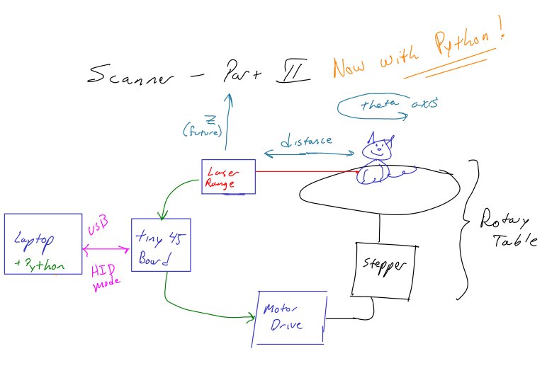
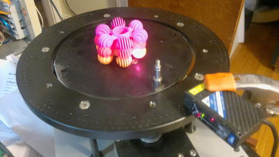
And here is a picture of the actual device:
Most of the components are were picked up here and there
surplus. The laser range finder was designed for checking
products on assembly lines (for example, measuring the height of a
glass jar lid to see if it is screwed on all of the way.)
The data-sheet describes measuring how many sheets of paper are in a
stack, so it may be pretty accurate. The output is an
analog 4-20ma current loop.
This week's progress...
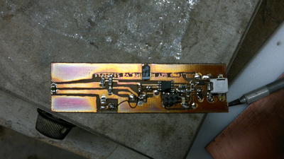
All of the above is interfaced to a tiny45 (new board designed and
etched. See hotplate solder below) which appears to a
laptop as a custom USB HID device. The microcontroller
takes commands, steps the motor, and reads the sensor -- sending the
results back to the laptop.
I played around more with the HID drivers... more specifically, the
software I wrote/modified last time was C based. This week
I spent a block of time getting the HID device readable under Python.
I also tried to improve the motor control on the
microcontroller side.
I also added some code to try to massage the data and plot the output
using pylab.
Results:
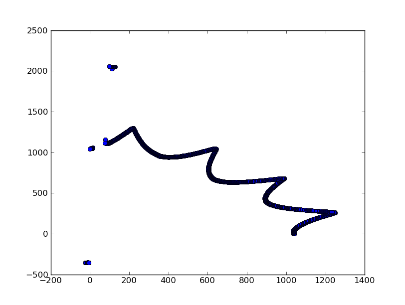
And here is what it thought it saw scanning a box:
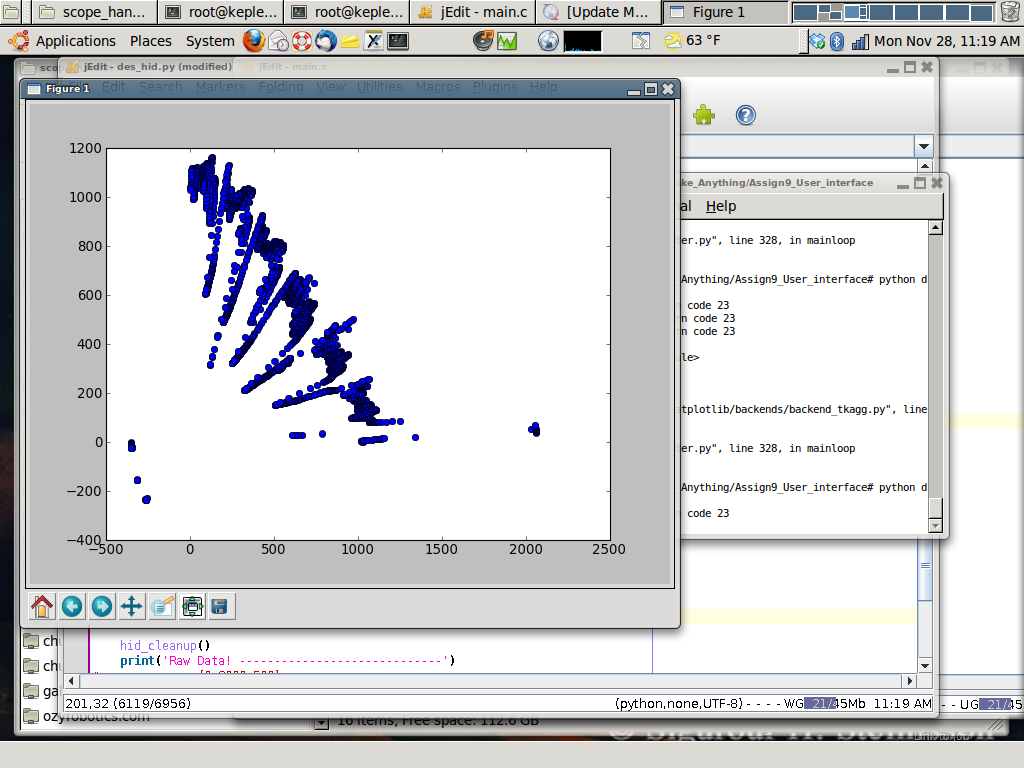
And here is a toy, and what it saw:
Additional Notes:
- Hotplate reflow (first
attempt)-- The solder kicked into liquid at about 160
degrees C It did an excellent job on the USB
connector! Solderpaste was applied to the board, components
were stuck on, and the whole shebang was tossed on a
hotplate. Result: great joints, 1 bridge. (a
nice reference:
http://reprap.org/wiki/HotplateReflowTechnique.)
- Reference explaining VUSB clocking on the Tiny45.:
http://vusb.wikidot.com/examples (see section titled:
- Clocking the AVR from the RC oscillator with
auto-calibration)
- USB Serial Reference Projects:
http://www.obdev.at/products/vusb/avrdoper.html
- TI DRV8811 Motor chips appear to have the same pinout as
the Allegro chips described on the MTM schematic. They may
run at reduced power, or have less operating modes.


