Shadow Puppet
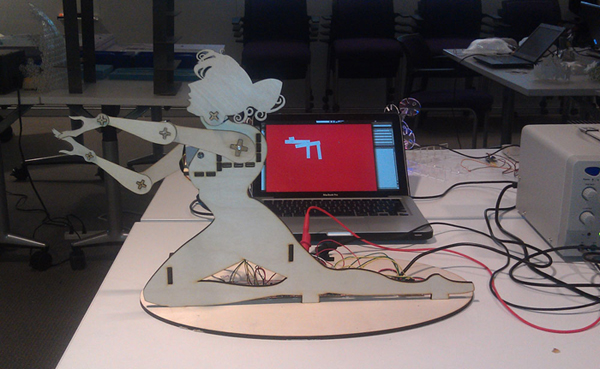
The goal of my final project was to create a mechanically actuated shadow puppet that is controlled through a GUI software interface
Step 1 | Developing a Stepper Motor Controller
Before I designed the actual puppet, I new my largest hurdle on the project would be to develop a way of simultaneously controlling numerous stepper motors. I selected the L293DD dual h-bridge chip as a motor driver, and designed a board that controlled a bipolar stepper with two logic inputs.
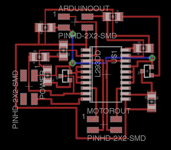
Board and Schematic files here.
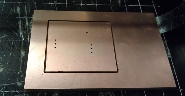
Traces and outline available here.
Step 2 | Building and Stuffing the Boards
Because the boards were going to be taking in 6+ volts, I was concerned about them heating up too much. I talked to brian who recommended connecting the chip ground to the bottom side of a dual layer board to act as an additional heat sink. I did this for the majority of my boards and then mounted them in a raised position to allow for air to flow underneath them and dissipate additional heat. I'm not sure how big of a difference this made in the end, but none of my boards overheated.
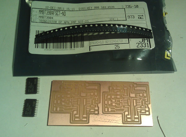
Aside from the L293DD, the boards also used NPN transistors to facilitate the switching between the coils of the steppers. Because of the design of the boards, you could also use n-mosfets which have the exact same footprint as the smd NPNs. I milled two boards to each sheet of copper. The total milling and stuffing process took about 5 hours total.
I originally wanted 7 points of articulation in my puppet, so I milled 7 stepper motor driver board and 2 fabduinos to use as controllers. In the end, I only ended up doing 5 points of articulation, so two of the drivers and one of the logic boards went unused.. there's always time over IAP though.

Step 3 | Designing the Puppet
The physical design was largely constructed in a manner to facilitate the varying sizes and shapes of the motors. I originally had 4 sizes of motors- 2 large 1.6" steppers for her shoulders, 3 0.8" steppers for her elbows and head, and 2 0.2" steppers for her wrists.
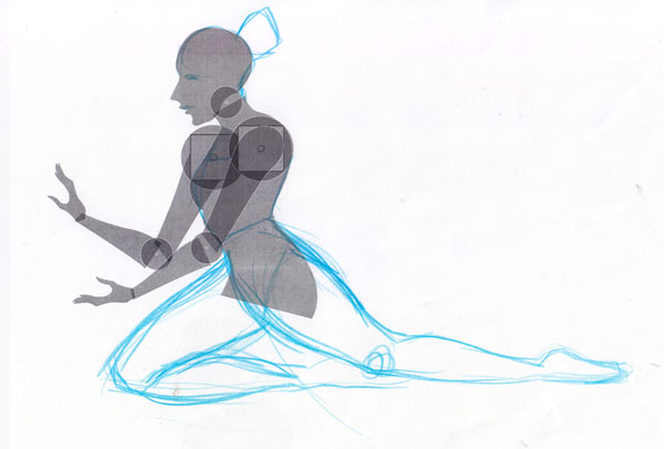
The entire design was structured to ensure the stepper could effectively lift the other steppers that were placed at latter points of articulation. I designed it in illustrator to be cut on the laser. The most challenging part of the design was devising a mechanism to attach the parts to the stepper spindles. I did this with press-fit cogs that fit tightly around the spindle itself.
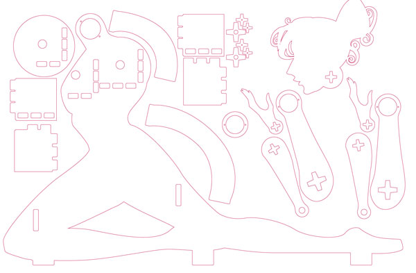
You can download the vector files for the puppet body here
I ended up not using the smallest steppers. I had no data sheets for them, so I had to guess at what voltage they were rated at. They were also poorly manufactured, so I had trouble connecting wires to them and even them, had to deal with their pins falling off regularly.

Step 3 | Building and Wiring
I tested each stepper driver with each motor- masking tape was my best friend during this step.
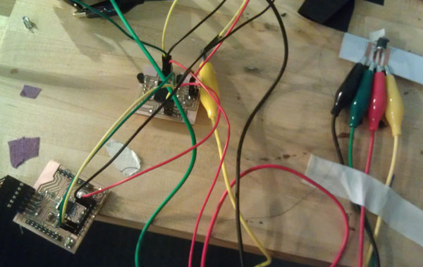
To wire the arms I had to ensure that each motor had sufficient wire lengths to allow for full rotations and still be connected to the drivers. I also had to allow for extra space in the motor fittings to allow the wiring to pass through.

I wired the puppet and setup all of the electronics on the rear part of the stand. This was easily the most complex part of the process and required a great deal of debugging.
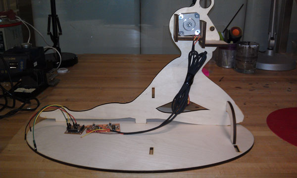
I connected the smaller steppers by sewing them into the puppet fittings. I realized that the medium steppers would need a greater degree of clearance to allow for full rotation of the arms, so I compensated by adding several wooden spacers to move them out further and away from the main body of the puppet.
![]()
Step 5 | Building the Software
I developed a basic Gui to control a single stepper using openFrameworks and a Fabdiuno. I've also wrote an initial inverse kinematics system for the gui:
OF kinematics stepper control from jennifer jacobs on Vimeo
I setup a basic parenting relationship between each arm and a virtual representation of an arm in the gui. The code functions by sending a serial code to the microcontroller, which triggers the movement of the corresponding stepper in the correct direction. Download the OpenFrameworks and microcontroller code here
Step 6 | Finished Puppet and Next Steps
The puppet functions by manipulating the gui representation to allow for corresponding movement in the physical puppet. Because I am sending commands via serial, there is a slight delay between controlling the interface and the movement of the puppet. I plan to compensate for this by sending byte commands rather than full serial ints. I also need to fully flesh out the GUI with a more representative set of graphics and develop a better method of calibration and zeroing.