Embedded Programming
Embedded Programming [EMB-ing]

Embedded Programming
This week involves ...
The following is a brief discussion of the topics introduced. The main computer architectures are the von Neumann(program and data same memory) and the Harvard Architecture(separate). The Harvard Architecture separates instructions and memory. The earliest architecture used a cpu which stored all the data, while the instruction was loaded by an operator. Instructions are generally stored in read-only memory and read-write will contain information that can be changed. Depending on how much data should be allocated for data and for instruction, addresses are sized accordingly to accomodate the system. In the von Neumann architecture, the CPU is doing one of two things: it will either read/write data from/to memory or reading an instruction. The Harvard architecture is faster because it means that the CPU can be doing both those tasks of read/writing and reading instructions at the same time.
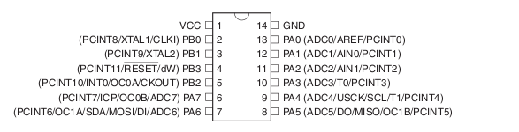
A microprocessor, which requires supporting chips, functions as the CPU on one IC, operating on binary, where it takes input, applies its own instructions and provides an output. A microcontroller is really everything on one chip which contains memory, processing and i/o peripherals.For How to Make, we will be focusing on milling/stuffing and programming our own microcontrollers. We will be using the ATiny 44, which costs about $ in bulk. Check out the 258 page datasheet. Who would think, 258 pages for a simple chip...or not so simple?
ATtiny44 DataSheet
Now that we have discussed the architecture of the IC, we can move on to the main components in IC architectures. In order to store any kind of program or data, we need memory. There are really two types of memory, volatile and non volatile.
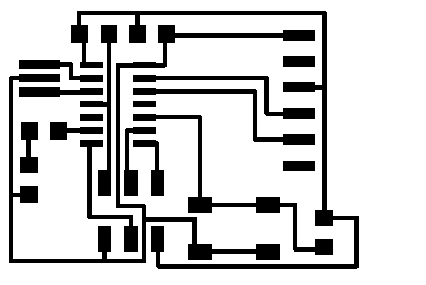
 We will use Eagle to setup the layout of our IC. In the following figure, you can see how to view both the schematic and board layout at the same time in Eagle.Do not close any window, you need both open simultaneously to edit both boards and allow changes to sync. To make connections through lines, we will use the 'Net'.
Route Command should be used in the Board Layout window, which allows you to draw a thicker line signifying a closed/through connection between two components. A yellow line means there is a logical connection in the schematic that's not on the board. The "rats" command looks for missing connections. If there is something missing in schematic that's not in on the board, then it will show up as a yellow line. The "Rip" command allows you to delete a line in the board layout.
 As illustrated in the figure above, once can only add components in the schematic layout. Type "Add".
Here are the main commands:
ERC
RATS
RIP to get rid of connection
RATS shows 3 airwires, then look for yellow lines.
When you add components and begin rearranging them in the Board layout, general rule is not to put anything on the bottom or left side of the board. Regarding connecting the button to the microprocessor, you don't want the button to just control the LED in a chain but make the button an input device, it can turn anything on.
A label equals a connection or a line equals a connection.
Zero ohm resistor trick- if you want to jump over a trace, you can do two layer boards, but for this class, place a zero ohm resistor.
RUN THE FOLLOWING 3 command once you THINK you are complete to check for errors.
1) ERC-checks logic
2)RATS on Layout-checks consistency
3) DRC-checks layout
FINALLY!!
Export as png
Make sure monochrome and 1000 dpi for resolution.


1)FABISP
2)FTDI
3)ARDUINO
Board has a 2x3 header, thats how you load programs, connect FABISP header to the one on your board. Plug FABISP in, make sure board you are trying to program is powered. The 1x6 header is for communication with the computer.