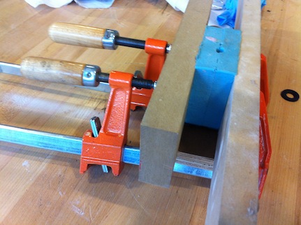
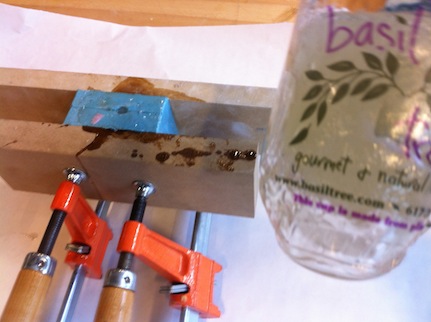
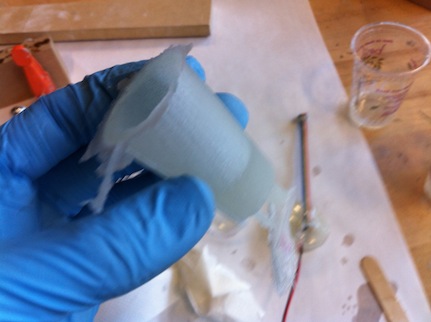
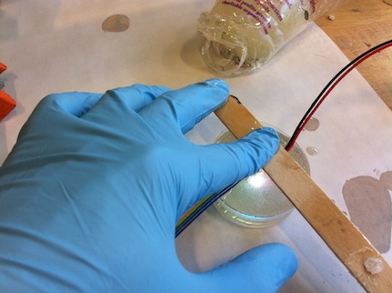
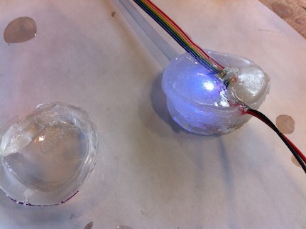
I also experimented with transparent/translucent casting resins. Smooth-On 325 is easy to work with and cures in about 10 minutes (it also has a pot life of only 2.5 minutes, so you need to be quick!). It accommodates PCBs very nicely, but it is not transparent but translucent. Its levels of translucency vary but even the best is not enough.
Final project
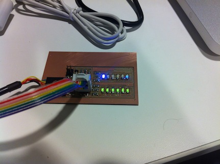
Working towards the final project, I designed a prototype of the board I'd use to power my LED glass. This board features a charlieplexed matrix and serial communication, a combination of Neil's hello.ftdi.echo.44 and hello.array.44 boards. The final circuit will feature more LEDs (10-15 of each color) and a controller with more pins. The LEDs will be soldered to vinyl cut traces that will run up the glass, while the rest of the electronics will be placed on a milled board at the bottom of the glass. The LEDs are charlieplexed in order to reduce the number of pins (used the the Tiny44 this time)
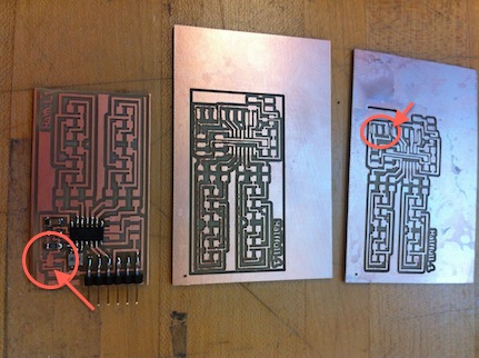
For the first time in my short milling career, my traces came out fuzzy on the Arch Shop Modela; replacing the bit didn't help. By crowdsourcing this to the MAS863 list I learned the following:
- Bits from the last shipment were not very good.
- Fuzzy traces could be straightened, to a certain extent, by scraping with a ruler, scrubbing, and washing.
- Very new bits, as well very old bits, tend to mill fuzzy traces, but reducing the milling speed helps. I followed Brian Mayton's recommendation: run the first job on a new tool at 3 mm/s, the next at 3.5 mm/s, and then go up to 4 for most of the life of the tool. When it gets old, reduce to 3mm again. That's the circle of life for you.
To be on the safe side I tried the CBA Shop Modela. Unfortunately, when I came to stuff the board, I found out some of my traces converged: apparently the 0.016 trace width I set in Eagle was too thick to go through the voltage regulator or the 2x3 header! Eagle actually tried to tell me that, reporting several collisions upon running DRC, but I thought I knew better. Turns out DRC is a reliable feature after all (unlike autoroute!). I went back to the drawing board, and adjusted my traces to 0.1 instead of 0.16, I even went as thin as 0.003 for the trace that goes under the voltage regulator.
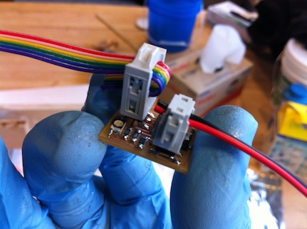
I re-milled twice on the CBA Modela: first with a 3 mm/s speed, next with a 3.5 mm/s speed. The first board came out straight and nice, but the board must have moved during milling, resulting in a skewed left side. The second board was pretty fuzzy wasn't properly cut out of its frame, but at least the traces were straight and didn't converge (see photos). I scraped it, scrubbed it, and verified with a multimeter that the traces indeed work. Stuffing was pretty quick.
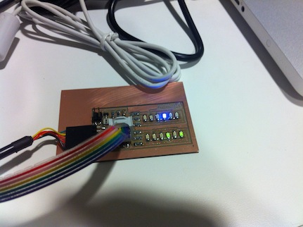
Programming was a bit problematic. First, I couldn't power the board through a battery so I used the FTDI cable for power (I left the GND and VCC traces connecting the FTDI header exactly for such cases). Then, to test the board I programmed it with Neil's hello.array.44 code, updating the pin numbers in the C code and setting the makefile for a 20MHz crystal. However, only a few LEDs lit up, and not very brightly. I first thought this was a hardware issue, but looking at the board schema I realized I configured the wrong pins in the code: I tried to power PA1 to PA6 instead of PA0 to PA5 as it should have been. A quick change and this time it worked! (see photos). Still investigating the battery issue though.
Update: thanks to Nancy's research on makefiles, I was finally able to resolve an issue I had a couple of weeks ago and use an array to store the charlieplex pin pairings. This allows more flexibility in controlling the matrix, and is particularly good for defining ranges of pins, etc. In a nutshell, to copy initialized arrays to the board, add the -j .data flag to the avr-objcopy command in your makefile (remove remove the -j flag altogether, including -j. text).
- Snap all components to grid: in layout view, go to File | Run... then open EAGLE_DIR/ulp/cmd_snap_board.ulp
- Design a new part:here's a good tutorial.
- Quickly locate airwires: hide all layers except for layer 19 ("unrouted") to show only the airwires. Toggle between this view and the all-layer view to locate the airwires and route them.
- My (little) experience shows that STOP MASK error can be ignored safely. Simply hide layer 29.
- Export to SVG (e.g., for editing larger boards using Inkscape): go to the User Language Program (ULP) download page on CadSoft's site. Download eagle2svg-1.2.ulp or similar (version might change). Now run it using File | Run...
