![]()
![]()
- 1. project description
1.1. General:
This week I wrote an application that communicated through serial with the light sensor that we made two weeks ago and uses them as parameters in a visualization in Processing. This week I focused on the coding aspect of the assignment. I developed a project which I had started in collaboration with Carl Lostritto last Spring, for Patrick Winston's Human Intelligence Enterprise class at the MIT Electrical Engineering and Computer Science Department. This project was a non technical experiment which involved people looking at various complexity computationally generated visual stimuli and sketching or verbalizing what they saw. We had written four different codes in Processing which all started from an array of recognizable glyphs (lines, points, concentric circles and filled circles) and then incrementally deformed them by increasing the influence of a random factor which was encoded in each of these elements. This is an image of all of the cards we had generated.
Figure 1: The various cards initially generated from four different Processing codes. "Complexity" levels 1-9
1.2. Application Design:
This week this week I combined all the card codes into one larger description, and added three buttons which allow the user to switch between three of the four visualizations in real time. This is what the application looks like for a given "complexity" level p; in this case p=2. You can get the full code here.Click here for a non-sensor-controlled demo
1.3. Sensor Values
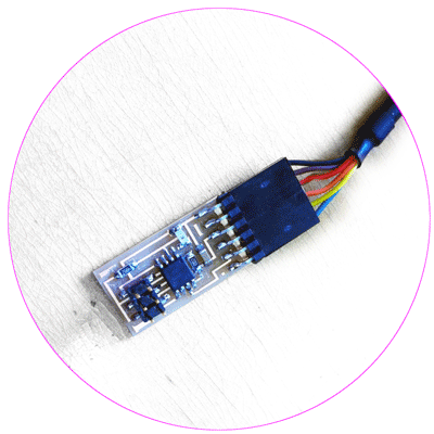
Figure 2: The light sensor
The sensor values are used to define the influence of the random function on the array of glyphs. In this way instead of creating cards from 0-9 complexity the one after the other, the users can see generate different "complexity' levels by moving their hand towards and away from the sensor.
Figure 3: Video of the application running; on the lower left corner you can see the changing sensor values
1.4 Code:
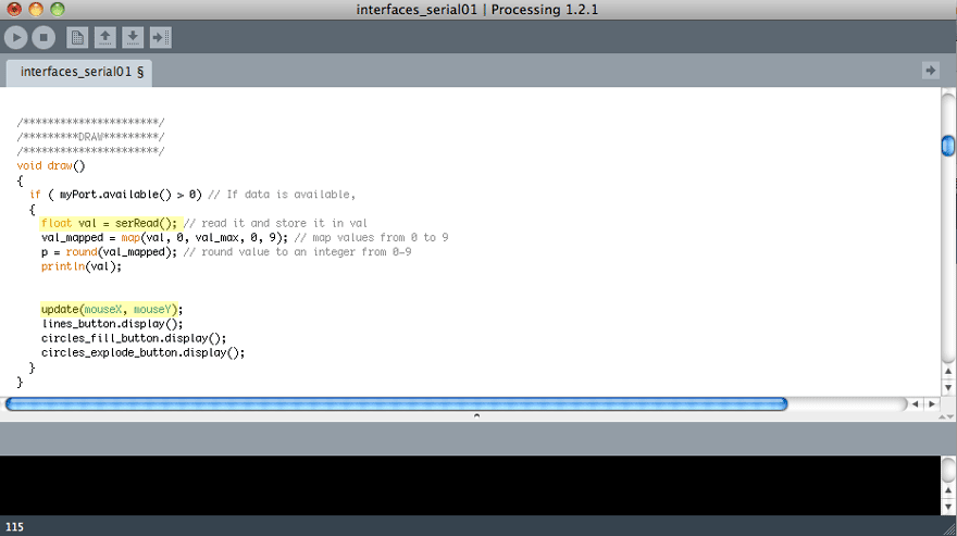
Below I am annotating snapshots of the application code.STEP 1: Declare different global variables. These refer to the serial port, the buttons that I will be using and the graphic elements of the visualization.
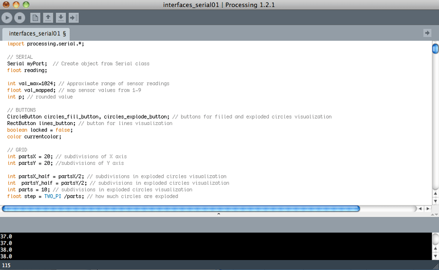
STEP 2: I will be using three graphic elements; lines, concentric circles and filled circles. These elements will have a latent random function in their description, in relation to their position. The sensor value will define if this latent function will be manifested. Below, I am declaring the three arrays of random values.

STEP 3: In the Setup I set the serial port by modifying the Processing Serial example. I also create the three buttons which allow the users to switch from one kind of visualization to the other.
STEP 4: In draw, I call the function serRead() to get the light sensor value. Then I map this value which can range from 0-255 to the 0-9 range that I will be using for the visualization. I also draw all the buttons and call the update() function which will register Button Actions.
STEP 5: Following Shaul's example I also wrote a method that only returns the serial reading after it has identified a correct pattern of 1,2,3,4
STEP 6: This is the update() function called in Step 4. When the mouse is over the area of the button, even without pressing it, it outputs the corresponding visualization on the screen.
STEP 7: Below are the different setups for the three graphic elements called with the different buttons. The primary function of these Setup methods is to initialize the arrays of the random values at the different spots of the grid.
STEP 8: These are the geometric specifications of the graphic elements. You can see the random number at each position encoded in their initial description, as well as the p factor that defines the influence of this random number. For the lines example there is an extra check that prevents all of the grid points from being deformed simultaneously so that it preserves a reference to its initial order for a larger part of the 0-9 scale.
STEP 9:This is the Button Class along with the two other classes, rectangle and ellipse button, which inherit from it. I used the Buttons example in Processing as the basis for the buttons.
> Controll Array through Button C Code: LED array is off when BUTTON is not pushed; the program keeps track of how many times the user has pressed the BUTTON since its launch and bases the delay of the LED array flashing on that
On Wednesday morning John and Tom gave us a tutorial on how to use the laser cutter. Here is a transcript of the notes that I kept along with some tips from personal experience.
3.1. Safety first:
It is quite usual to see a small flame when the laser is cutting the material. If a small flame worries you then you can open the lid and cover the flame with a piece of acrylic. If the flame is big or the material catches on fire then you open the lid, close the air valve and call 100.3.2. How to put the material on the laser bed:
The origin point is the top left corner. Make sure your material is the right size; in the Universal Laser Cutter at the CBA shop the bed is 32*18". You might need to use some tape to attach the material to the edges of the bed if it is not completely flat (this is for example very usual with cardboard)3.3. How to adjust the height of the laser bed:
Use the marked metal rod to measure the height between the cutting tool and the material you have placed on the laser cutter board. Press Z and use the Up and Down arrows to bring the cutting material to the edge of the metal rod. You will know that the height is right when the pin does not let the board to go any further up.
The check button moves to smaller digit precision for height refinements with the up and down arrows. Once you have found the right height press Z again to exit.3.4. How to send your files:
3.4.1. If you are using Inkscape:
1. Prepare your file and export it in 300dpi. Keep in mind that the white part is the one cut with precision so your offsets are "eating" off the black part.
2. Go to fab > run in terminal
3. Select the Universal laser cutter and define power and speed. Make sure that you set the pulses per inch (ppi) to be less than 500 if you are cutting cardboard. If you are cutting acrylic you can do almost 300.
4. Specify xmin and ymin. This is how far from the top left corner (origin) the machine will start cutting the file.
Hit make .uni
6. Send!3.4.2. If you are using CorelDraw (Windows):
1. Import your file
2. Make sure all your lines are Hairline (No thickness)
3. Optional step: You might want to offset your lines for precision. Go to Effects>Contour and do an Outside offset of 0.005 (or around that) Then do Arrange and break contour group apart.
4. Go to File>Print>Properties and set Power and Speed per color
Press Set to register your changes
6. Print!3.4.3. If you are using Rhino or AutoCAD (Windows) you can set the speed and power per layer through the print menu. Make sure you SKIP all the layers you do not want to cut and that you select the area you want to cut with a print window and that all your lines are 0 thickness or hairlines. In Rhino you can set the size of the print window and then Move it in the correct spot in the screen. You send your file by hitting print.
3.5 How to cut your files:
Find the right file! If you send multiple files you can navigate through them with the >> and << buttons.
2. Do a test run. It is recommended that you do a test run to confirm that the path is right. Just press the green button <|> while the lid is open.
3. Cut! If all looks fine close the lid and press <|> to cut.