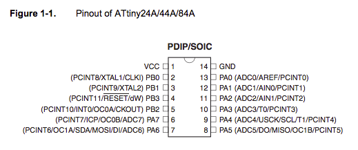
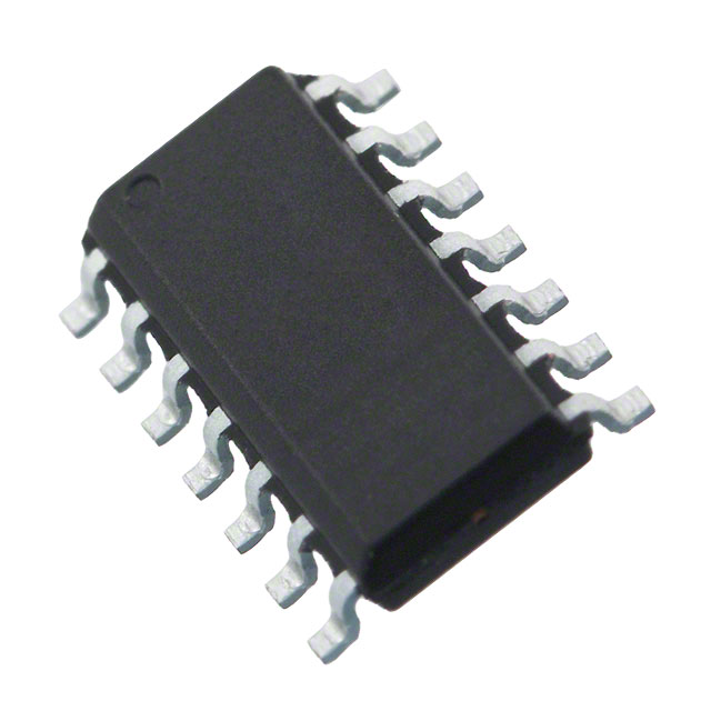
The star of the show is the microprocessor, the ATtiny44A
.

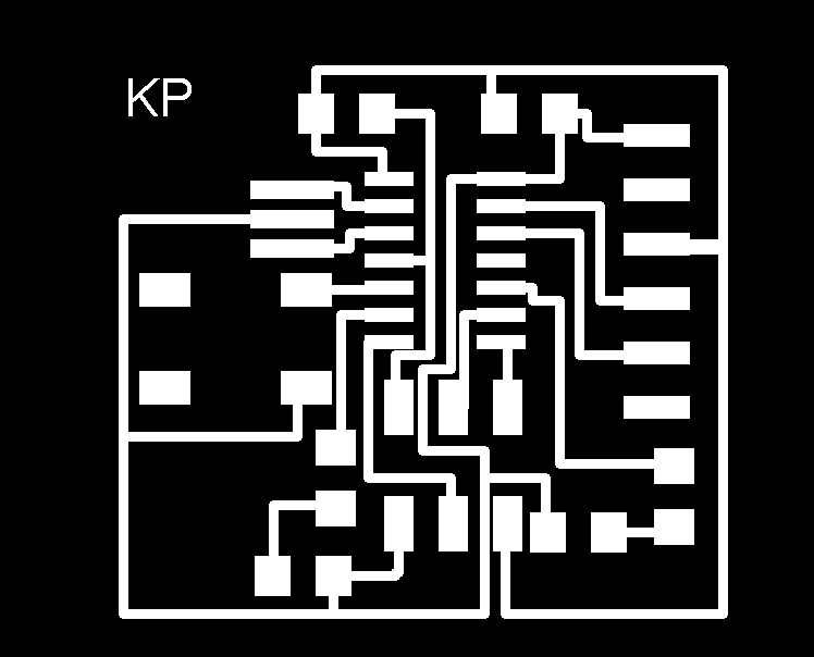
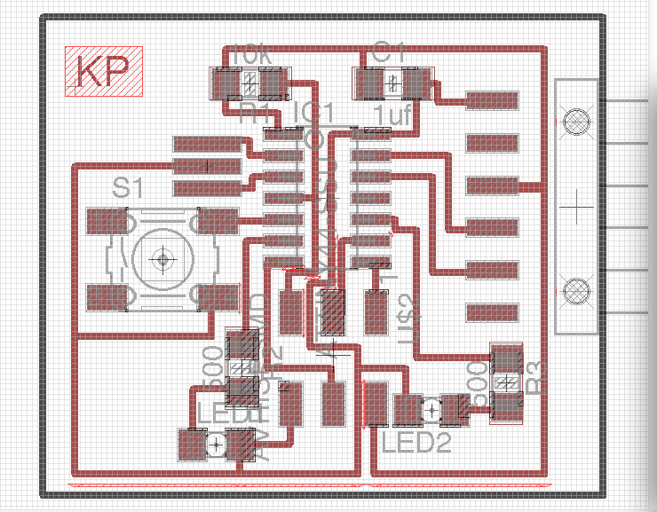
Circuit Designed in Eagle PCB Design Software
Pin Anatomy
Main Power Lines
1. VCC = Power
14. GND
Taken Up
2/3 Resonator
4. 10k Resistor
7. MOSI (AVR)
8. MISO (AVR)
9
SCK (AVR)
Extras
5. Switch (button)
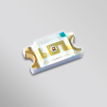
6. LED1
10. LED2
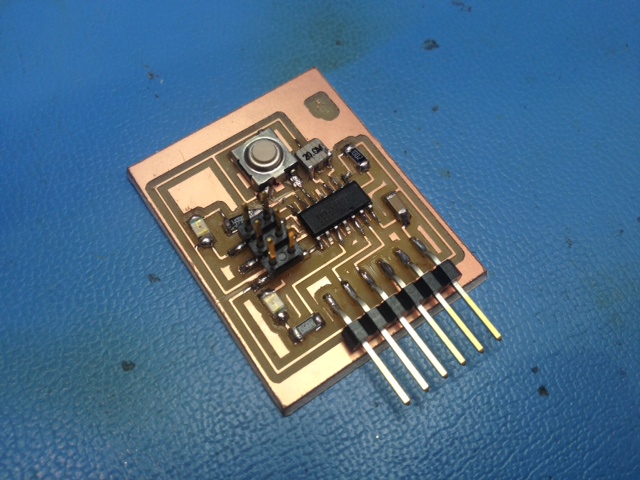
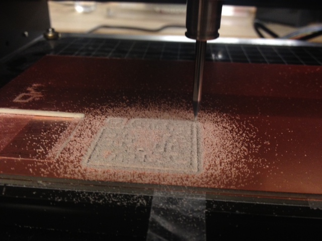
Step 1 is to put all the pieces you need on the board and make all the connections.
Step2 is to lay out all the traces so they don't cross over. If you must, you can use a 0 ohm resistor to jump over a copper trace.

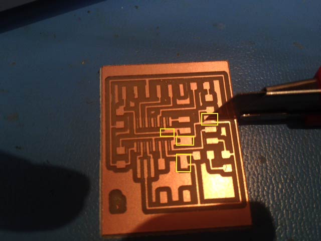
I thought I finally got a good one, but many of the traces were actually connected where they shouldn't be where they were too close. The software did warn me about this. Next time I will pay better attention.
Since I was running out of time... I decided just to split these connections by removing a section of the copper with an exacto knife. I had to be really careful but it worked ok.