EMOTIONAL DESIGN LANGUAGE ORB
This prototype is an early experiment looking into how the changing design language of objects, in particular their form, can be used as a means of communicating meaningful information through the medium of objects.
This Emotional Design Language Orb builds on my research to map different elements of the design language in objects to the emotions that they evoke (visualised in the Emotional Design Language Map* below). This prototype starts to explore how these 2D visualisations can be translated into a tangible 3-dimensional object, using coloured light and actuated composite structures to change the colour and form of the orb, reflecting the different design language of varying emotions.
Angry |
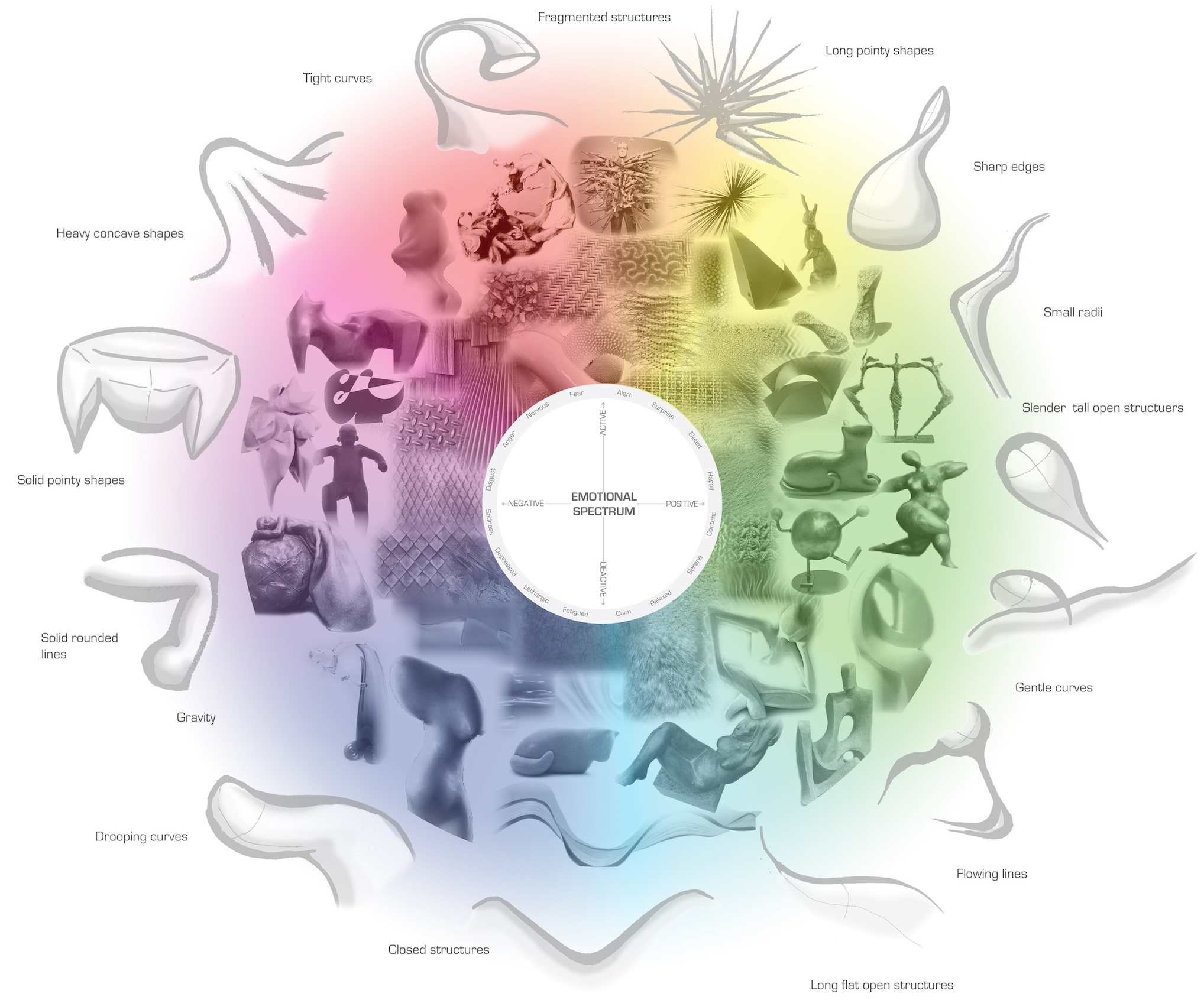 *Emotional Design Language Map - formal and textural design language representing different emotions, based on Russell's circumplex model |
Happy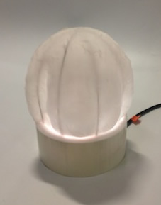 |
Sad |
Serene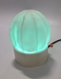 |
|
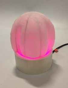
The design of the Orb aimed to change the form from a smooth sphere to a sharp ridged shape - representing smooth flowing lines for a 'happy' emotion, and sharp ridged concave shapes for a more 'angry' emotion. In this early prototype, a small form change was achieved from a smooth round shape to a more uneven ridged shape. Future iterations will aim to improve on the definition in this change in shapes, to communicate information more effectively through the design language and form of the object. |
||
INSPIRATION
CONCEPT
Ambient Devices - David Rose |
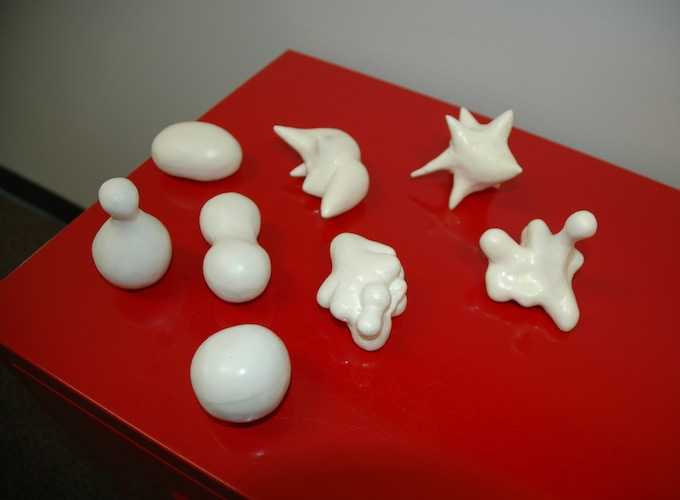
Sensual Evaluation Instrument 'blobjects' - Katherine Isbister and Kia Höök |
|
TECHNOLOGY
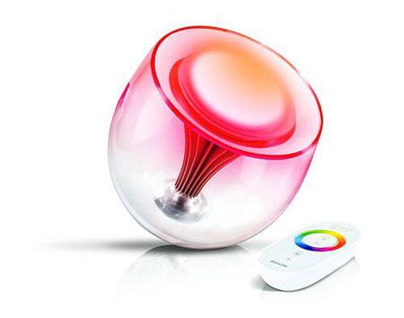
Philips light - colour changing light connected to colour wheel input
|
Christopher Black - Expressions
|
Erik Demaine - origami/silicone structures
|
|
||

AESTHETIC
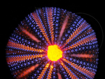
Changing colours - Coral, bioluminescence
|
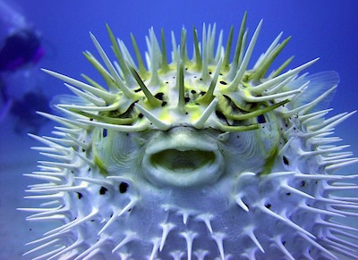
Changing shapes to communicate messages - puffer fish, cactus
|

EARLY DEVELOPMENT
TECHNOLOGY COMPONENTS RGB LED AND SERVO: circuit board and fab inventory parts - Fabduino parts, RGB LEDs, MOSFETS, servo (trial with: arduino servo) INTERFACE FOR RGB LED AND SERVO: Processing SHAPE CHANGING FORM: origami and then make fibres and fabric/silicone cast based on this movement, servo movement moves form *MATERIALS NEEDED: EcoFlex SuperSoft Silicone 0030* |
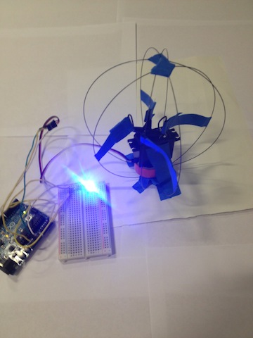
EARLY TRIALS RGB LED AND SERVO:initially prototyped using an Arduino and breadboard and these helpful tutorials - electronics design and pwm program, and processing to control servo INTERFACE FOR RGB LED AND SERVO: here is the initial connection of the RGB LED and servo to the colour wheel Processing interface. As the mouse pointer is moved around the GUI, the colour is read in and transmitted to the LED, and the servo moves from 0 to 180 degrees. |
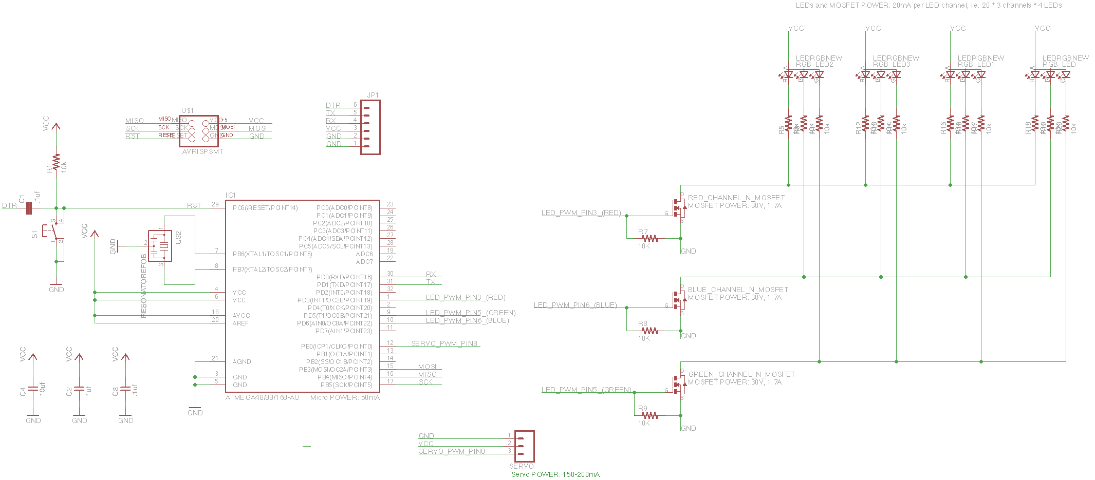
HARDWARE DESIGN: I have translated this breadboard prototype into a schematic for a PCB:
I will test this design out and then potentially make some modifications - adding a MOSFET, maybe adding more LEDs |
SHAPE CHANGING FORM: origami and wire trials |
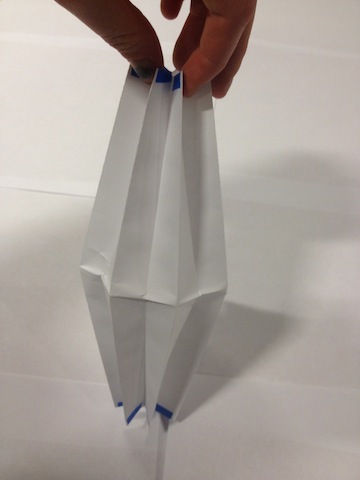 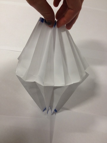  |
servo actuating wire frame - changing shape of ball from round (and smooth) to ridged |

FINAL DESIGNS
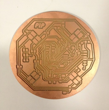
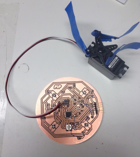
RGB LED AND SERVO CIRCUIT BOARD in the modified schematic I routed each of the R, G and B channels on the LEDs through resistors and a MOSFET to amplify the signal to the LEDs. I also did some schematic maths to ensure that I wasn't overloading the board:
|
|||
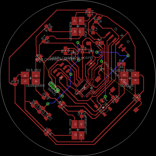
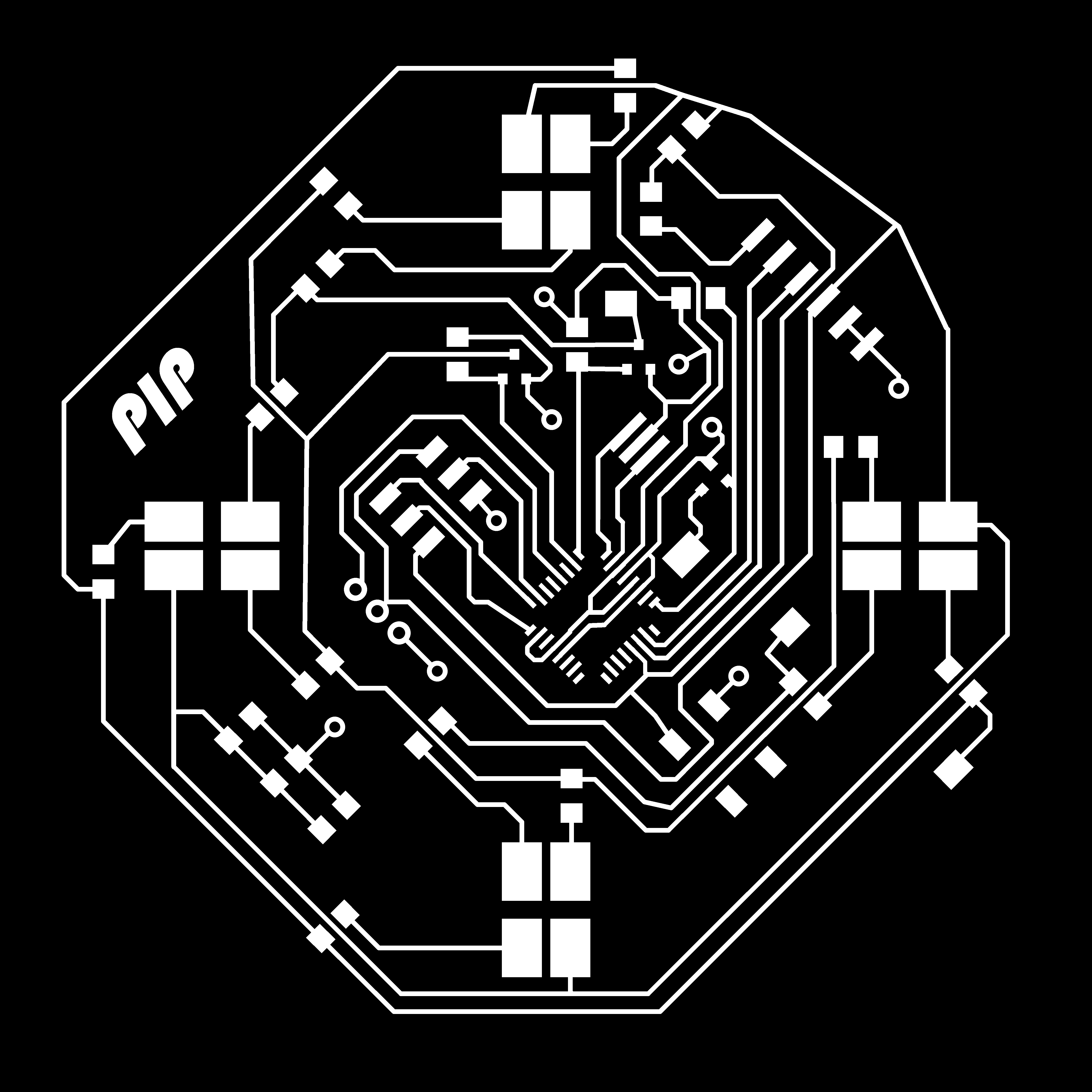
A double sided board: |
|||
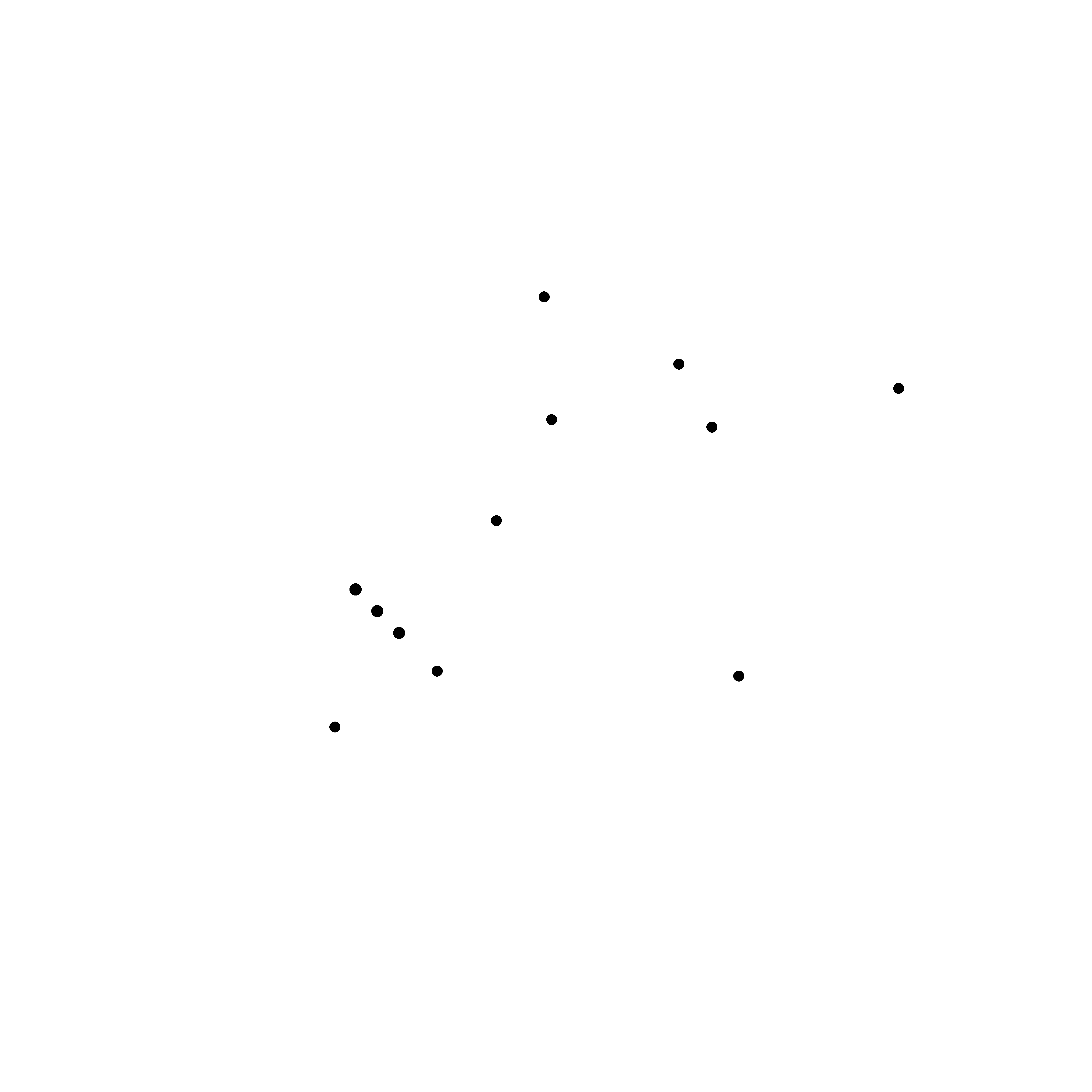
Holes (vias to connect GND to bottom surface): |
|||
  |
|||
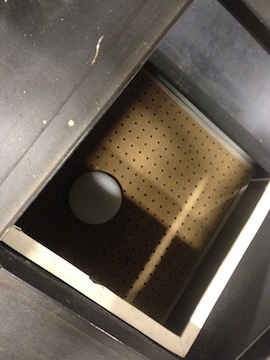
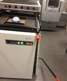
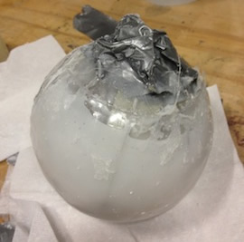
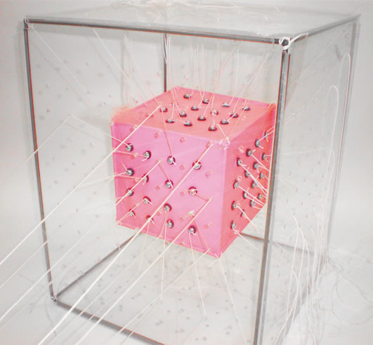
SHAPE CHANGING ORB I built on the wire experiment by casting the wires in a spherical shell of silicone. This form with 8 circular wires cast evenly around the sphere should transform the form from a smooth sphere to a ridged ellipsoid - like the cactus ball. Making a spherical shell mould using the vacuum former:
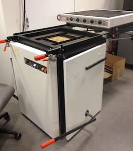
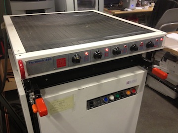
USING THE VACUUM FORMER: |
|||
The vac former (next to the laser cutter): |
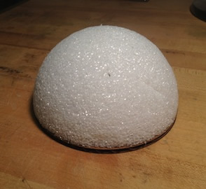
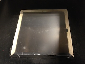
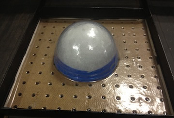
Your mould (with no undercuts): |
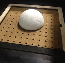
Put your mould on the bed: |
Lower the bed by moving the arm on the side vertical: |
|
|
|
|
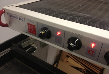
Put a sheet of vac form plastic onto the foam pads on the bed and lock cover with the clamps: |
Turn on the heater in the areas you need and wait to heat up: |
Pull the heater over the plastic and leave for 5 mins until slumped: |
Pull the mould up to the soft plastic and press the green Mould button: |
|
|
|
|
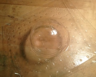
Wait for the plastic to form to the mould and cool down a bit, then turn the Mould button off and press the Release button: |
Release the plastic from the mould: |
||
|
|
||
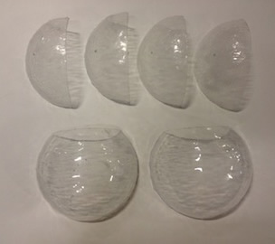
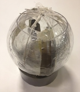
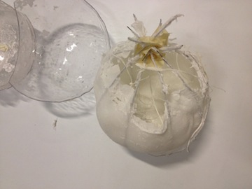
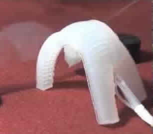
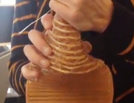
Here are the vac forms which formed my mould. I cut the inner mould into 4 sections to remove from the cast easier, and cut a small section from the top of both the inner and outer shells to pour the silicone in. I also drilled some small holes in the bottom of the outer sphere sections for air holes. I covered the wires with adhesive tissue before casting them to make them stick to the silicone more. To assemble the mould, I taped the inner sphere sections together, then tied the wires around the inner sphere, pulling strings through very small holes in the inner sphere to actuate the fibres once cast. I then hot glued the outer sphere pieces together around the inner sphere and wires and added lots of tape to the edges at the top to act as a funnel for pouring the silicone into the mould. Demoulding the cast was a little fiddly and delicate, but tapioca flour helped to stop the silicone sticking to the mould.
|
|||
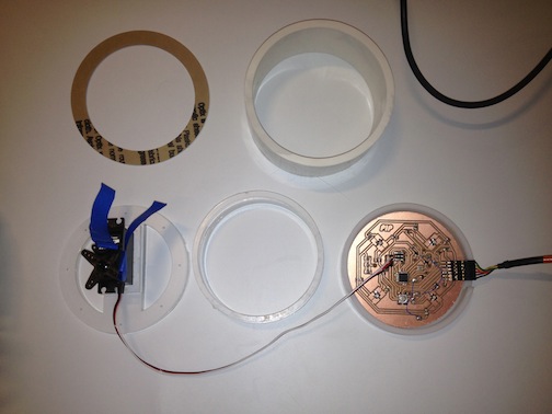
BASE FOR ORB The base for the orb encloses the electronics and servo. I made it from a piece of plastic pipe and laser cut acrylic, to allow as much of the light from the LEDs to filter up into the orb as possible. |
|||
  |
|||
INTERFACE FOR RGB LED AND SERVO Same as above - using Processing and Arduino files toread in and transmit the colour to the LED as the mouse pointer is moved around the Emotional Design Language Colour Wheel image, and the servo moves from 0 to 180 degrees. The colour and shape change of the orb aims to map to the design language of different emotions - round and smooth for happy feelings and more pointy for angry emotions. |
|||
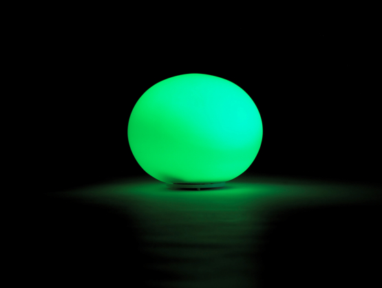
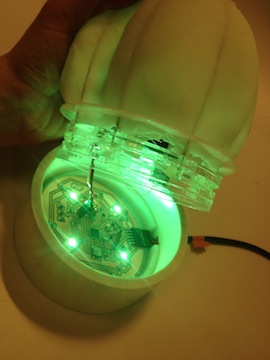
Serene: green and smooth |
Angry: red and ridged |
Happy: yellow and smooth |
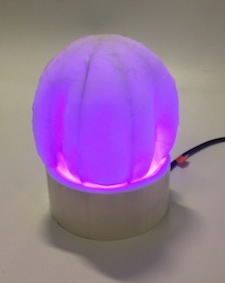
Sad: purple and ridged |
THE FINISHED PRODUCT A physical orb which tangibly communicates the design language of different emotions |
|||