A FAB ISP MICROCONTROLLER PROGRAMMER
WHAT (ON EARTH) IS A FAB ISP?
A quick glossary for those not au fait with electronics abbreviations! (with links to useful sites for further explanations)
| FabISP |
A DIY in-system programmer |
| ISP (In-system programmer) |
A circuit which can program a microcontroller (and other programmable circuits) whilst in a complete assembled circuit - rather than programmed in the chip before assembled into the full circuit. Very useful for testing and changing the program after the design has been assembled. Just like an Arduino! |
| Microcontroller |
A small computer on a single circuit board which contains a processor, some memory and some input/output (I/O) connection points. It is a self-contained system in comparison to the separate microprocessors, memory and I/O points which you would find in something like a personal computer, and therefore simpler and cheaper to use |
| A PCB (printed circuit board) |
A support material with embedded traces (paths in the electrical circuit) onto which the components (e.g. resistors, capacitors, microcontrollers etc) can be soldered to |
| Surface mount components |
Electronic components which can be soldered flat onto a circuit board (in comparison to through-hole components which you'd generally use in a breadboard or a circuit board with holes drilled through) |
HOW TO MAKE A FAB ISP
|
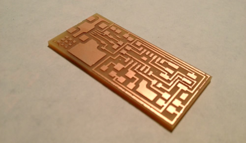
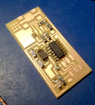
1: MILL THE CIRCUIT BOARD
Here are the steps for milling a circuit board on the Roland Modela machines:
- Stick your circuit board to the baseplate in the Modela using double sided tape. **NOTE: Make sure your board is as flat as possible - I positioned mine in the middle of the base as the corner was bowed up slightly**
- Secure the mill end into the mill **NOTE: Initially secure it very high in the mill so that you don't hit it on the base or your board when positioning it**
- Open Fab module and open the Roland Modela app
- Load your circuit image
- Set path type to which mill end you're using (1/64 for etching traces and 1/32 for cutting the board out)
- Find the origin of your board by altering x and y min positions so that the mill end is at the bottom left corner of where you would like to cut
- Zero the z height of the mill end by unscrewing it and re-positioning it on the surface of the board **NOTE: Re-do this process at different positions across the board to make sure you've got the minimum z height all the way over the board**
- Make rml path and go!
- Repeat this process to cut out the board using the 1/32 mill and outer trace
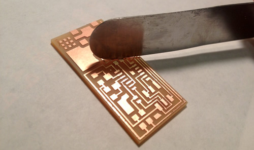
- To remove the burs from the milled board lightly scrap them with the metal spatula
|
|
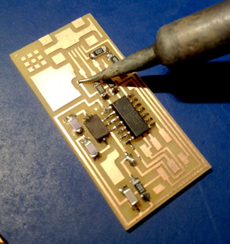
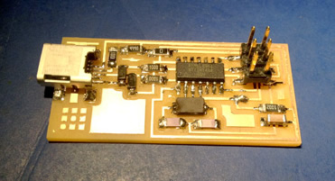
2: STUFF (I.E. SOLDER COMPONENTS TO) THE BOARD
- Collect the surface mount components from the lab **NOTE: Resistors and diodes are labelled with their values but capacitors are not so remember which is what!** (Jumpers are just 0Ohm resistors or a bit of solder connecting the two points)
- Soldering surface mount components is fiddly! Here are some tips:
- Work in a space with LOTS of light!
- Heat the area of the trace where you want to solder to with the soldering iron
- Apply a small amount of solder to this trace (without a component)
- Hold your component where you would like to solder it on the board with tweezers and heat one end of it and the pre-applied solder - this should melt the solder and make it flow to the component, soldering one end of it to one side of the connection and tacking it in place so you can securely solder the other connectors
- Heat the other end of the connector and trace and then melt some solder onto both
|
 |
3: PROGRAM THE ISP
This is how you program the microcontroller in the circuit for it to be used to program other circuits.
- Download and install the CrossPack AVR (if working on Mac OSX) - this is the code library that is needed to program the microcontroller
- Download the firmware data - this is the code which specifically runs the programming function for the FabISP circuit
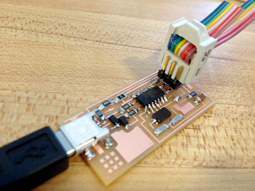
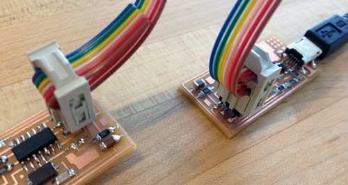
- Plug your ISP into your USB port with a USB to mini-USB connector - this powers the board
- Connect your board to another board which has already been programmed and their jumpers desoldered with a ribbon wire to the pin connection points (at the opposite end of the board to the USB connector)
- In Terminal:
- Navigate to your firmware folder (if it is saved in your User directory then just type: "cd firmware" - cd means change directory)
- Then type: "make clean" - I think this just clears the folder of any old
programming files
- Then type: "make hex" - this creates the binary code for the microcontroller
- Then type: "make fuse" - not sure what this does
- Then type: "make program" - or this
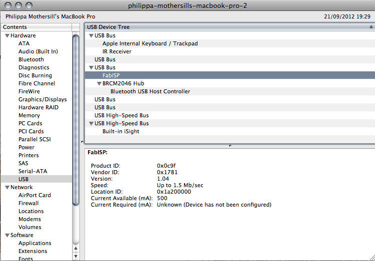
- Check if your FabISP is working by looking for it as a registered USB port:
- Go to System Profiler (More Info in About this Mac)
- In the USB contents you should be able to find your FabISP
|
| |
4: DESOLDER THE JUMPERS
|