WINKING LED CIRCUIT BOARD, PART II

This week I tried to understand embedded programming so that I could program the winking LED circuit board I made in Wk 5 - particularly the workflow from my brain to a winking LED on a circuit board when using different development environments.

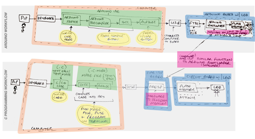
Here's my sketch of the workflow process for the Arduino and C development environments - nice and simply laid out so you can understand what each component in the process does, and how the different environments wrap them up, and what programs you have to use/what you have to do at each of these steps:

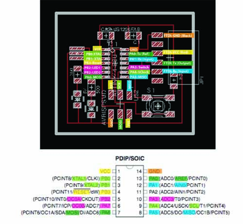
HOW TO PROGRAM YOUR ATTINY CIRCUIT BOARD USING C PROGRAMMING WORKFLOW

I found Laia's tutorial very helpful in downloading all the right software, and Travis's page for the code to make it blink.


1: WRITE YOUR CODE

Here is my C code and Makefile that I used to program my circuit board (see opposite) - I used a modified version of Neil's code with help from Travis. Here are some tips:

  • Look at the data sheet to find the pin references on the microcontroller you are using, so you can match them up to the switches and LEDs on your circuit, and then define them as inputs or outputs in the code
  • Pins marked PA need to be defined as PINA, PORTA, DDRA, and pins marked PB need to be defined as PINB, PORTB, DDRB


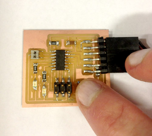
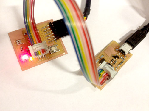
2: CONNECT EVERYTHING TOGETHER

  • Connect your computer's USB port to your FabISP mini-USB port with a USB-A to USB-B cable - this takes the hex made from the avrdude run by the Makefile from your computer and loads it onto the FabISP Attiny44 chip
  • Connect your FabISP ISP header pinouts (the 2x3 array of pins) to your circuit ISP headout pinouts using a rainbow ISP cable (making sure ground goes to ground - check your schematic!) - this connection allows the Attiny on the FabISP to talk to the Attiny on your board and program the memory on your board
  • Connect your FTDI port (the 1x6 array of pins) on your circuit board to your computer's USB - this powers the circuit board (once you've uploaded the program to the Attiny on the circuit board, you can remove the FabISP cables and just use this FTDI cable to power your board)

Philippas-MacBook-Pro:Wk 7 - programming pip$ make -f blinking.led.c.make
avr-gcc -mmcu=attiny44 -Wall -Os -DF_CPU=20000000 -I./ -o blinking.led.out blinking.led.c
blinking.led.c: In function 'main':
blinking.led.c:43:37: warning: unused variable 'i'
blinking.led.c:43:27: warning: unused variable 'count2'
blinking.led.c:42:19: warning: unused variable 'pwm'
rm -f blinking.led.hex blinking.led.eep.hex
avr-objcopy -O ihex blinking.led.out blinking.led.c.hex
avr-size blinking.led.c.hex
text data bss dec hex filename
0 222 0 222 de blinking.led.c.hex
# avr-objcopy -O ihex blinking.led.out blinking.led.c.hex;\
# avr-size --mcu=attiny44 --format=avr blinking.led.out
Philippas-MacBook-Pro:Wk 7 - programming pip$ sudo make -f blinking.led.c.make program-usbtiny-fuses
Password:
rm -f blinking.led.hex blinking.led.eep.hex
avr-objcopy -O ihex blinking.led.out blinking.led.c.hex
avr-size blinking.led.c.hex
text data bss dec hex filename
0 222 0 222 de blinking.led.c.hex
# avr-objcopy -O ihex blinking.led.out blinking.led.c.hex;\
# avr-size --mcu=attiny44 --format=avr blinking.led.out
avrdude -p t44 -P usb -c usbtiny -U lfuse:w:0x7E:m

avrdude: AVR device initialized and ready to accept instructions

Reading | ################################################## | 100% 0.00s

avrdude: Device signature = 0x1e9207
avrdude: reading input file "0x7E"
avrdude: writing lfuse (1 bytes):

Writing | ################################################## | 100% 0.00s

avrdude: 1 bytes of lfuse written
avrdude: verifying lfuse memory against 0x7E:
avrdude: load data lfuse data from input file 0x7E:
avrdude: input file 0x7E contains 1 bytes
avrdude: reading on-chip lfuse data

Reading | ################################################## | 100% 0.00s

avrdude: verifying ...
avrdude: 1 bytes of lfuse verified

avrdude: safemode: Fuses OK

avrdude done. Thank you.

Philippas-MacBook-Pro:Wk 7 - programming pip$ sudo make -f blinking.led.c.make program-usbtiny
rm -f blinking.led.hex blinking.led.eep.hex
avr-objcopy -O ihex blinking.led.out blinking.led.c.hex
avr-size blinking.led.c.hex
text data bss dec hex filename
0 222 0 222 de blinking.led.c.hex
# avr-objcopy -O ihex blinking.led.out blinking.led.c.hex;\
# avr-size --mcu=attiny44 --format=avr blinking.led.out
avrdude -p t44 -P usb -c usbtiny -U flash:w:blinking.led.c.hex

avrdude: AVR device initialized and ready to accept instructions

Reading | ################################################## | 100% 0.00s

avrdude: Device signature = 0x1e9207
avrdude: NOTE: FLASH memory has been specified, an erase cycle will be performed
To disable this feature, specify the -D option.
avrdude: erasing chip
avrdude: reading input file "blinking.led.c.hex"
avrdude: input file blinking.led.c.hex auto detected as Intel Hex
avrdude: writing flash (222 bytes):

Writing | ################################################## | 100% 0.21

avrdude: 222 bytes of flash written
avrdude: verifying flash memory against blinking.led.c.hex:
avrdude: load data flash data from input file blinking.led.c.hex:
avrdude: input file blinking.led.c.hex auto detected as Intel Hex
avrdude: input file blinking.led.c.hex contains 222 bytes
avrdude: reading on-chip flash data:

Reading | ################################################## | 100% 0.13s

avrdude: verifying ...
avrdude: 222 bytes of flash verified

avrdude: safemode: Fuses OK

avrdude done. Thank you.


3: RUN THE MAKEFILE IN TERMINAL

Here are the commands I used in Terminal to run the Makefile which takes my C code, compiles it using gcc, and uses avrdude to upload it to the FabISP:

  • Navigate to the folder where your files are using the cd command (if you don't know the name of the file you can use ls -a to bring up a list of all the folders and files in the directory where you are currently located in Terminal - it should tell you this in the intro line)
  • Type: make -f blinking.led.c.make
    • This should check the code for errors before compiling and list them out in the terminal if any exist
    • It should then create a hex file
  • Type: sudo make -f blinking.led.c.make program-usbtiny-fuses
    • This should prepare the chip to write
  • Type: sudo make -f blinking.led.c.make program-usbtiny
    • This writes the program to the chip


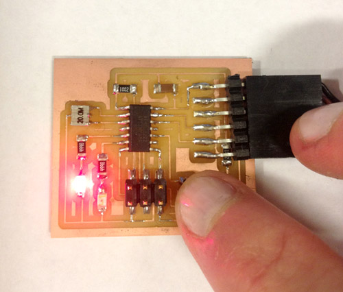
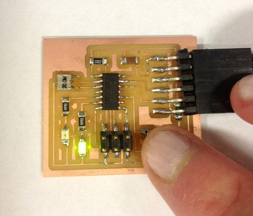
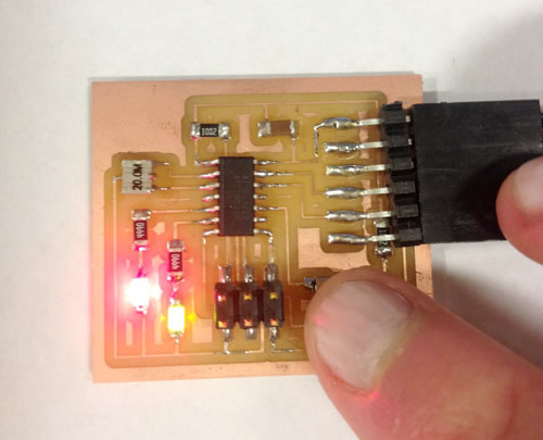
4: BLINK YOUR LED!

The code should now be loaded onto the chip on your circuit board now, so you can disconnect the FabISP from your circuit board. As I had two LEDs and one switch on my board, I wanted to program the 4 different combinations - both off, red LED on, green LED on, red and green LEDs on - to come on one after the other when you push the switch 4 times.


At the moment my code doesn't take into account the clock cycle in the chip, so pushing the switch gives you a bit of a random chance of which mode - none, red, green or both - that you'll get.