Beginning an investigation into the assembly of cubic lattice structures with discrete scaffold units. The primary objective is to identify an assembly strategy with simple kinematic alignment. This initial test was an attempt to limit the assembly strategy to unidirectional alignment for each orthogonal lattice plane.
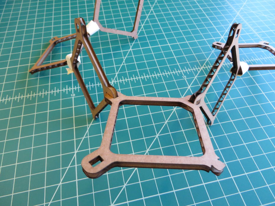
Cardboard is an effective prototype tool for planar part construction as it can be rapidly and precisely cut with a laser, resulting in effective an inexpensive prototype components.
From the outset I wanted to use a parametric modeler - a CAD program whose features are numerically driven tracked through a feature heirarchy. This is important because it is important to be able to iterate prototypes; often times interface dimensions need to be tweaked and it is helpful to build a design that automatically scales all of its features based on say the thickness of the construction material. This is the type of design tool around which I have spent the last five years building a career. My current design superpowers are contstrained within the commericial product SolidWorks - an industry standard for machine component design. It is unfortunately, a rather expensive tool and has a bit of a learning curve. An opensource alternative package does happen to be currently under development: FreeCAD. I have checked in with this package at various points over the past couple years and have seen it is under significant development and has shown immense improvement. The intent of FreeCAD is to be not only a parametric modeler, but one that is readily accessible through a Python API. This last subject is something I find very interesting, as I see the future of mechanical design integrating programmatic design into the traditional parametric process. Now don't get me wrong, I still believe designers are visual and want to retain the ability to actively drag and drop design components. That said, I think more younger engineers are growing up with stronger programming skills and this framework opens up the possibilty for implementing not only iterative features but declarative design - where exact details are not specified, but rather intent, and software fills in the minute details - liberating the designer to focus on the more complex and creative details of an assembly. Declarative design is something I am very interested in seeing developed - if you are interested in this subject please contact me as I would love to establish a team of programmers (who are obviously more skilled than I) to develop these types of design tools.
As it turned out, I ended up using Solidworks for this proejct when I realized I needed to complete the task and found that both FreeCAD seems still a bit buggy and a bit of a learning curve for this weeks development timeline.
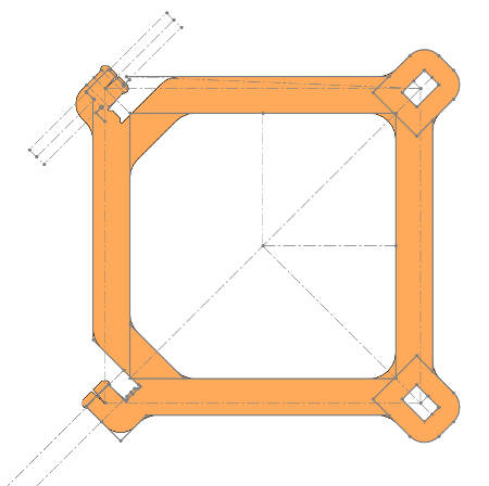
The images above are taken from SW and shows my general design methodology: any time there is an interface between more than one part I draw that interface in a sketch. I then build parts off of those sketches. In this way there are just a couple sketches to go back to to make modifications that are reflected throughout the depths of the design. It should be noted that because design constraints can drive many features further along the path it is important to strategize how to build the sketches and parts ahead of time and often multiple iterations are required. The part above shows sketches that define the thickness of the cardboard so that each interface is updated by a single dimension. Additionally, the interface points are aligned such that the center of interface aligns with the center of the scaffold arms that connect to each of interface components.
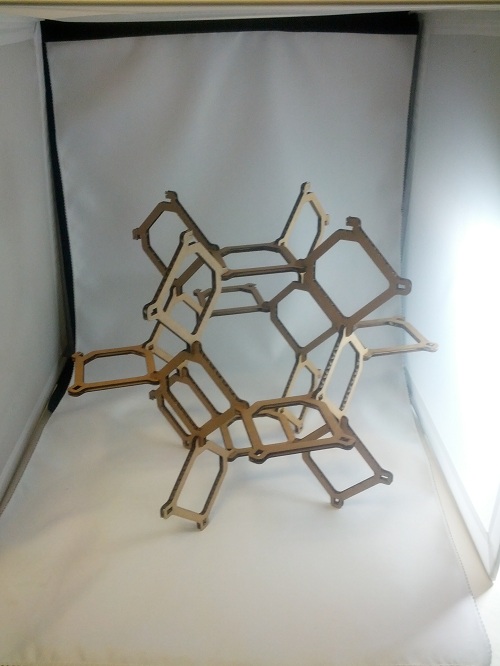
Combination of these square units forms the Kelvin Structure. While complex appearing, it is actually formed by arrays of alternating squares aligned corner-to-corner along alternating orthogonal planes. This structure seems conveniently suited to digital assembly as a single degree of freedom may be necessary for part placement. The arrangement of interface joints was the main point of investigation this week. The question being: is it possible to order the placement of parts such that a single motion is necessary to place components?
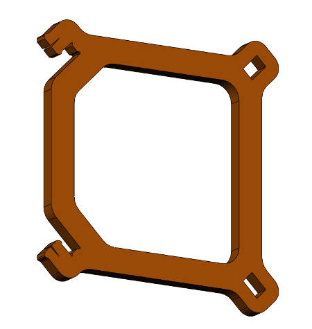
To that end, multiple iterations were made. Initial iterations were to establish the proper material thickness and locking configuration that matches material thickness and laser cutting kerf adjustments. The final locking mechanism included a slight taper with a preloaded detent shape to help hold the the pieces in position against a kinematic stop. The second set of iterations were to establish the orientation and number of interlock features. Initially I thought a pin, hook and double hole configuration would work (visible above). I quickly realized that the pin was not effective in fixturing in the orthogonal direction - something I should have realized ahead of time, but alas prototyping turned out to be faster than over thinking the problem! The next two strategies included double hooks and holes, with hooks aligned in rotation together and in counter rotation to one another. Interestingly both configurations are compatible with eachother in the assembly, and neither solves the problem of single degree of freedom assembly! So, back to the drawing board.