Project 3: 3D Scanning and Printing
There are a number of ways to scan an object and it seems like every other day a new 3d scanning company is starting up with either a new technology or a conveniently packaged older technology. Most of all of these technologies operate on four distinct concepts: laser, structured light, time-of-flight, or photogrammetry. The first two of these are really the same technique but with different methods of generating similar point clouds - collections of points with known x,y,z cartesian coordinates. This week I evaluated both laser and photogrammetry techniques as sometime last year I had already played around a bit with a strucutured light system.
3D Scanning - LASER
A relatively straight forward method of scanning an object in three dimensions is to locate the x, y, z coordinates of points all along the exterior surfaces of the object by triangulating the point location from a known distance and angle between laser and camera. There is a great description from a roboticist, Kurt Konolige, et al, whom I happened to have worked with at Willow Garage, that explains the concepts. In the CBA shop we have two laser based scanning systems that are designed for scanning desktop sized objects utilizing the technique described in the paper above. Both of these scanners rely on a stationary laser and a rotary stage to be able to collect data on all sides of the object.
An interesting thing about using lasers is that the light is structured and coherent - the photons leaving the laser unit are unidirectionally aimed and travel with minimal divergence. This means that scans can be done with high accuracy at significant size variation - limited by the accuracy of the measurement of spacing, laser divergence, and camera resolution. So, while it is possible to can scan desktop sized items in our shop, it is also possible to scan the surface of the earth with lasers on satellites in space. This technique is refered to as LiDAR and the data is freely available thanks to our US tax dollars and of course USGS, JPL and I imagine other entities.
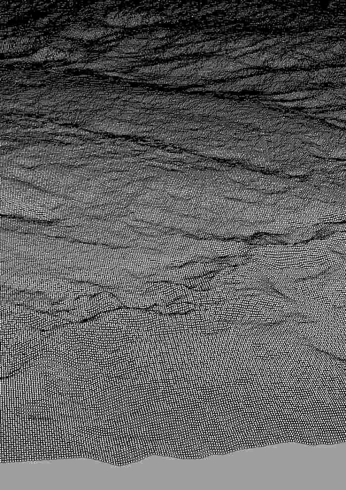
I spent a fair bit of time looking into collecting elevation data and generating surfaces to be used for random art projects. Unfortunately, I actually found it rather difficult to convert the collected data types into something I understood how to use in either Rhino or Solidworks. Digital Elevation Map data is relatively straightforward, except that it is sometimes formatted in binary with various headers. This is something I am still learning to deal with. There are some very sophisticated and even opensource GIS softwares available; but with their sophistication also comes a significant learning curve. I did play with an add-on to Rhino/grasshopper, called ELK, in an attempt to filter the data points. This was mildly successful but I am still learning grasshopper and found it surprisngly difficult to generate a raw xyz data file with my busy schedule. At some point I will carve otu time to sit down and get this work flow solved for myself. Raw data is available from the following sources:
3D Scanning - Photogrammetry
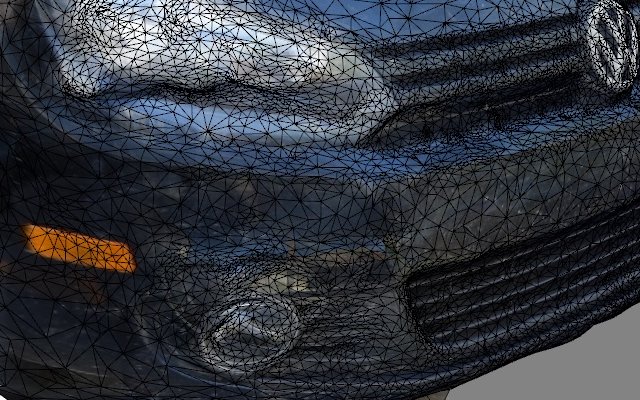
I also experiments with photogrammetry, where groups of digital images are taken of an object and these are stitched together to generate a 3D mesh of the object. It is important to gather some of the background in the images such that the software has some information to back out the location of the camera. It is quite fancy seeming, with texture (color image) mapped back onto the mesh - this makes the mesh look far more detailed than it actually is. I wanted to try this technique because I need to make a front license plate holder for my car. I figured I could scan the front of the car and then offset from those surfaces to build a form fitted component. I made three attempts at this and found some interesting notes. Highly reflective surfaces definitely throw off the mesh, but if there is enough data it can get a rough surface built. The relfections showed up as very strange indentations or whispy growths.
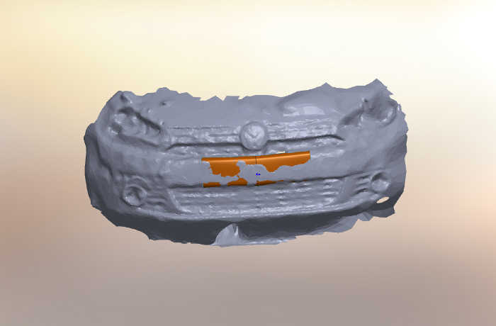
I also tried bringing the files into Rhino and Solidworks. Again, I don't know my way around rhino very well yet! So, I switched to Solidworks I was able to draw splines to approximate the shape of the bumper, visible above. What is noticeable is that there is such variation in the mesh geometry it is very difficult to identify the actual structure beyond a bulk shape. I tried to build the surface in an average location but I still don't feel comfortable with this feature. I was hoping there would be a tool in Rhino to average a smooth surface across the mesh, alas I'm sure it is there but I've got a lot of digging ahead of me.

3D Printing - Makerbot and Form Labs
As it turns out, I've actually used a fair number of 3D printers over the past number of years including the following: Stratasys FDM, Envision Projet, ZCorp, Objet, SLS, and now Form Labs. In my opinion the SLS is the ultimate 3D printer with the capability of making parts with high resolution from engineering materials such as nylons and even metals. However there does seem to be some warping that can happen during post processing of the SLS. The next best machine is the Objet printer that has minimal post processing, very accurate resolution and relatively strong ABS-like materials - and also interestingly it can print flexible materials. The ProJet is very similar to Objet, but the support material is a wax that requires melting for removal - which can cause warping of the part if care is not taken. I'm not a huge fan of FDM machines due to their limited resolution due to their nozzle size requirements for the filament. FDM is also highly directionally sensitive to part strength and accuracty. The Form Labs printer is very interesting as it has very high resolution, but post processing is rather messy.
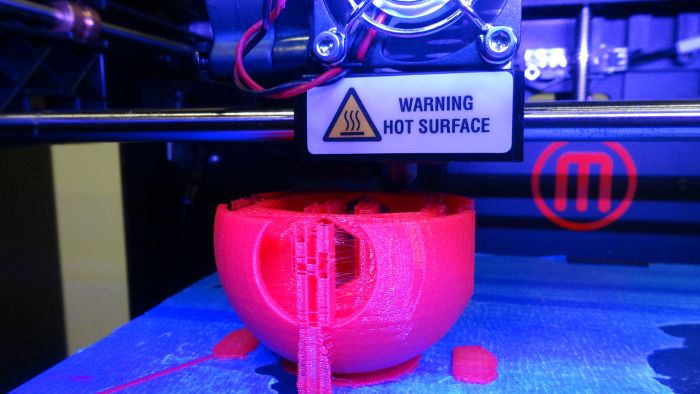
The thing with 3D printers is that they allow the user to design and make parts with geometry that cannot be fabricated with traditional manufacturing means - for better or worse. The task this week was to design and print something that is otherwise unmakeable. I chose to use the Form Labs printer to print a trophy that we had attempted to print a year ago on a Form Labs printer at some ridiculous conference in the Virgin Islands. Unfortunately, we ran out of time at the conference and were unable to print the parts. I mention the conference because I was invited to give a talk on parametric modeling by my friend Jonathan Bachrach. At this talk I met Matt Keeter, who suggested I consider CBA as a career path - and well now I'm here! So it's worth making the trophy for the event organizers that they never received. The printer was busy at the time so I decided to print a copy on the Makerbot (I had not yet used one).
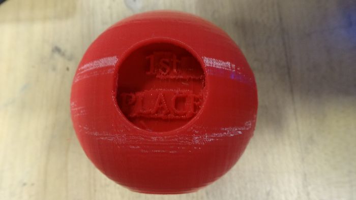
A noteable thing about the Makerbot is that I could not find any features that allow me to control the support material buildup as is possible in every other 3D printing system I have used. I imagine this is for simplicity. However, the support material caused some unexpected results as is the central hole in the part which I had cleared to reduce material usage ended up being full of support material.