Project 4: Make Something Big - ShopBot Gantry Router
This week we're supposed to make something big with a gantry based cnc router system. The primary differences between a router and a milling machine is generally the Z-height clearance and rigidity of the system. A mill is massive because it is designed to cut primarily metals which are stiff. The natural frequency of vibration of the milling machine structure needs to be well away from the high frequency vibrations induced during cutting. A router is generally used on softer materials, such as woods, plastics and foams. The vibrations induced by cutting are much lower frequency and so the structure can also be less stiff (lower natural frequency). The router is a good cnc machine to learn on because the softer materials are much more forgiving on both the tools and the machines - as will be shown later. There are different levels of CNC milling, 2D, 2.5D, 3D and mills and routers come in each of these varieties. The difference between these is that in 2D the mill can be computer controlled in x and y axis but must be manually moved in Z at each step. 2.5D is when a mill can operate in two degrees of freedom at a time, x/y, y/z, x/z but not all three simultaneously. The Shobot is capable of full 3D motions which means it can make some nice looking features.
I have had a lot of experience operating 2D cnc mills, and I have had a lot of 3D parts made, but I have not actually operated a 3D cnc myself but maybe once previously. Since I am already quite familiar with machining and assemblilng parts I decided to focus on 3D profile machining - something I have wanted to spend more time developing, rather than assembling an object with OSB. (I did however begin to design something very massive that will be built over the next week or two - to be unveiled then.) This is the process of machining The overall process is as follows
- Design a 3D part and save it as an STL.
- Load the part into a toolpath generator. Shopbot ships with Partworks 3D.
- Generate roughing toolpaths
- Generate finishing toolpaths
- Locate raw material on the machine
- Load the toolpath onto the machine
- Cut some stuff!
- Remove the part
- Perform finishing operations
Design a 3D part
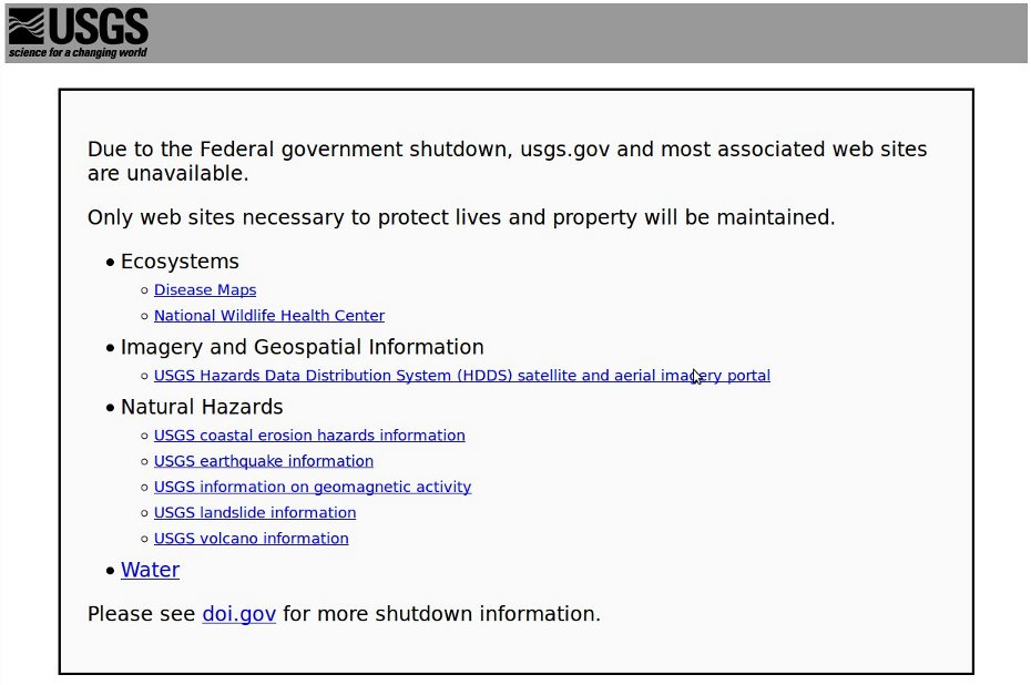
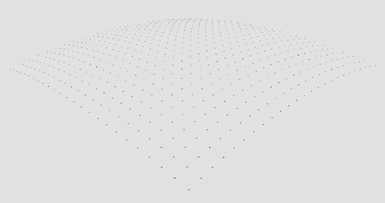
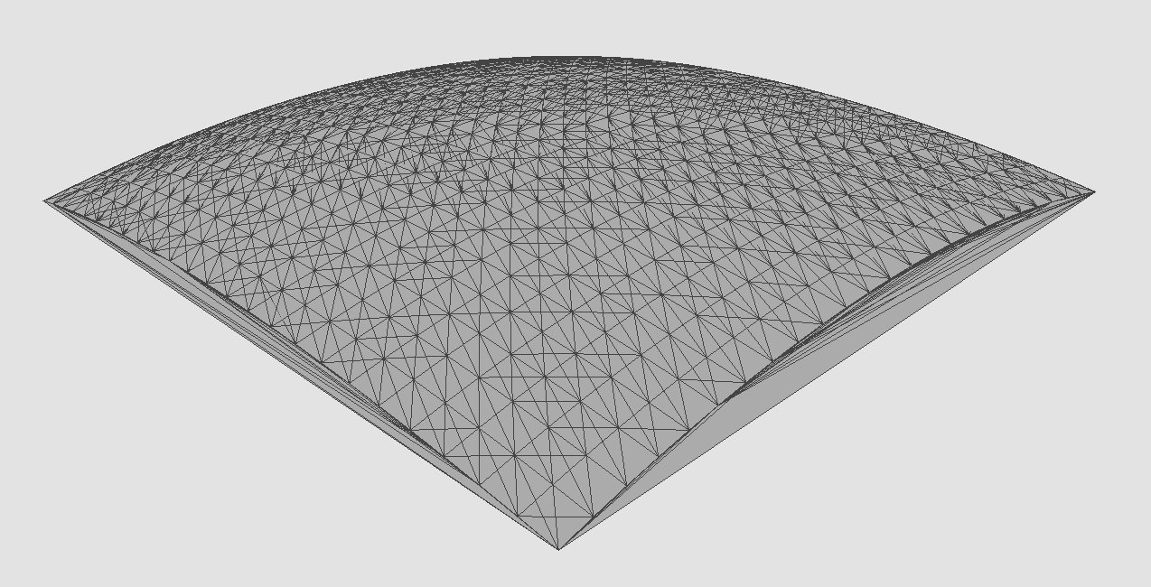
So I have always had a thing for surfaces with curvature and sharp edges. I have also had a bit of a fascination with elevation maps. I think maybe the two come from my favorite terrain, the hills of California. Lately, I have been spending a fair bit of time attempting to retrieve digital elevation data that has been collected by USGS and converting it into a surface map. It turns out to be surprisingly difficult to find a reader of the various data formats and often times the readers are much more sophisticated (and complicated) than I need for my purposes. So, I finally think I found an almost decent workpath to collect LIDAR data from NASA/USGS and generate an XYZ collection of points and generate a surface. So, this week I go to start working on this and what do I find? A freakin' government shutdown. The gov't shutdown my art project - the bastards!
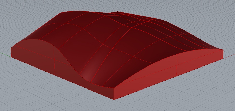
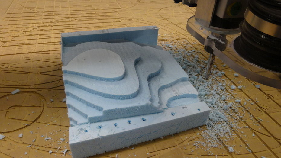
So, instead I through together a quick random surface in Rhino and took it to the machine. So I could be sure to have something to cut.
As it turns out later (like the night before the assignment was due, when I should have been doing robotics homework) I decided to start figuring out how to generate my own point clouds and stl files programmatically. I wanted to make the feet for a passive dynamic walker. I first tried doing it with Kokopelli, but I realized I didn't understand how to generate the dual curvature surfaces (Sam recommends a torus! I'll try again later when I have more time). I then decided to write a python script to generate the surface from the function described in the paper above. Nonetheless, I did manage to generate a point cloud and I was able to open it Meshlab and generate a surface around the points. I also got the idea that I should write my own STL generator - for the hell of it. This is where I realize I really have a long way to go with re-orienting my mind set around recursion, loops and arrays! I got confused and decided I need to get back to doing homework - to be revisted later.
Make Parts
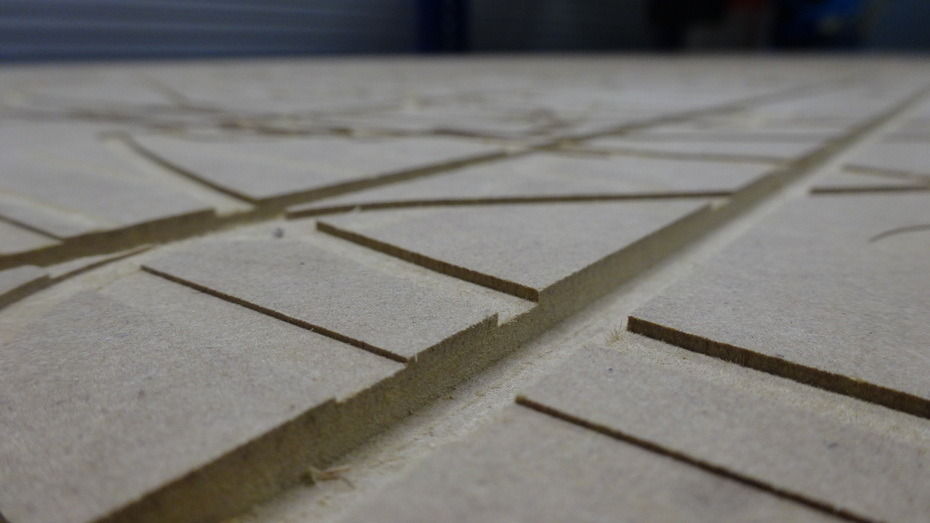
A note to users of the shopbot: /rant-on Please check your cut depth!!! Adjust it if it is too deep, you only need to just cut through your material. This picture below shows someone just clobbered the fresh surface. Granted the MDF surface is sacrificial, it doesn't mean it needs to be sacrificed with every use, it should last a long time. When it gets deep gouges such as this it means other users may have a hard time keeping their parts flat. /rant-off
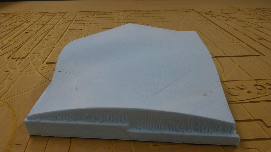
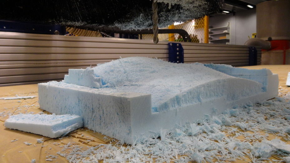
My part was about 4 inches tall, so I laminated two pieces of insulation foam with a 3M general purpose spray adhesive. It worked reasonably well, but the two surface did separate in some places. I then screwed the foam to the sacrificial surface and proceeded to rough cut the material.
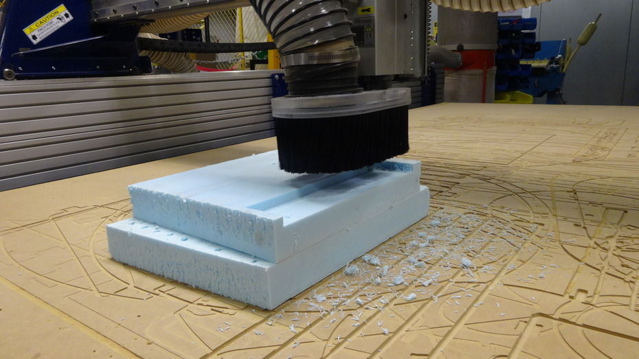
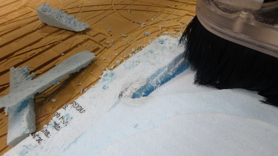
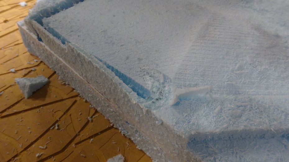
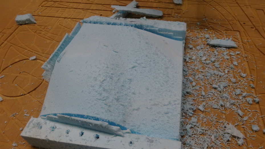
A note on Partworks. It is very simple and easy to use. But with this simplicity comes the lack of control, such as there is no where to describe the length of cut of a cutter. There is a bit of a work around to not machine all the way down. Next time I'll be more careful as we can see later another high spot rubbed on the collet. In metal this would be catastrophic, in foam it's just a nuisance.
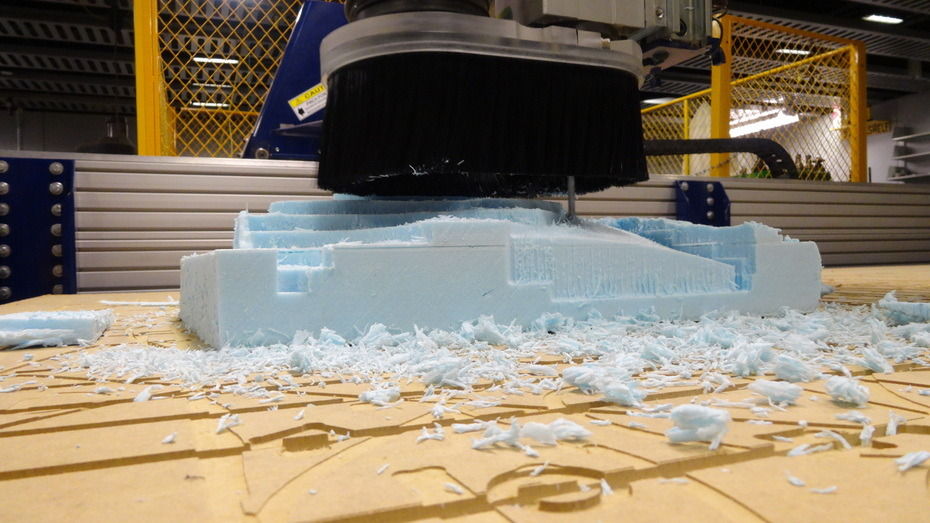
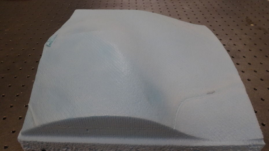
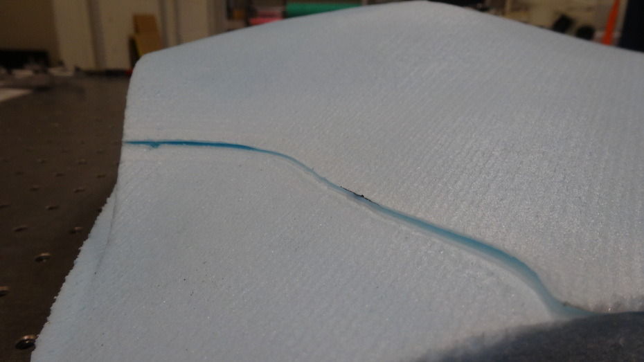
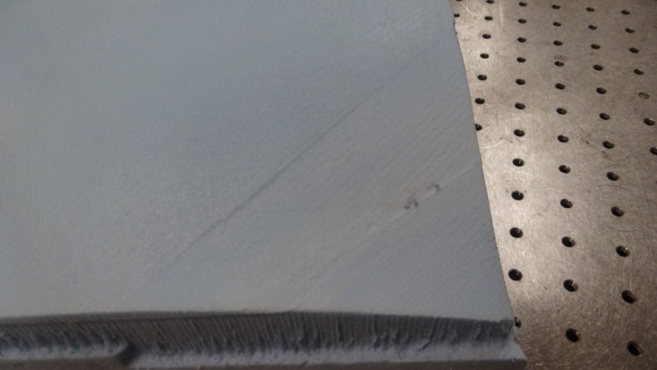
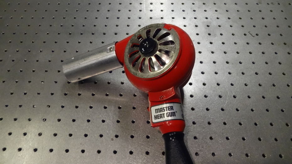
I tried the technique of taking a heatgun to the foam to tighten the surface. It sorta works. I used a hightemp heatgun used for solder rework and it was a bit too focused and too hot. Then I used the big red heatgun shown below and it tightened up the surface to some extent. But not all the way.
150 ton Hydraulic Press - This is coming later
Stamp forming steel/aluminum is the process of straining a metal beyond its yield point but before its ultimate strength. Somewhat non-intuitively, Aluminum, while a softer metal, is actually more difficult to stamp due to its limited ductility - even a soft formable allow such as 5052 H32, commonly used for sheetmetal, will only strain up to 18% before failure. There are interesting high strain-rate techniques used in the automotive industry where hydraulic fluid or even explosive techniques are used but this is much to exotic for the student shop. Steel on the other hand can strain at rates of roughly 40% (alloy dependent), and is as such, possessing greater formability.
There have been a number of occasions in the past where I've wanted to stamp form features and I have not had the capacity nor the quantities to justify sending the parts out to manufacture. Prototype stamping sometimes needs to happen. Additionally, I've had a thing lately for wanting to stamp interesting 3D surface profiles. So, when tasked to build something big for How to Make Almost Anything, I realized, I should make one of the tools I've been wanting.
Running the numbers I realized it is actually rather difficult to identify pressures necessary to stamp a square foot, since it really depends on the features, their depth, dimensions, etc. being pressed. I was initially thinking I need to generate 30,000psi across the entire face such that I could yield the entire sheet, but this turns out to be an insane amount of force. So I decided I would just build as strong of a press as seems reasonably possible.
I jumped onto a surplus website and located some 4" bore hydraulic cylinders, a bunch of hoses and fittings and immediately purchased them. I then started running numbers and realized that a 4" bore cylinder would generate 100,000 lbf at 2000psi - too much. I decided I should scale back and I found a 3" bore cylinder that actually had more convenient mounting clevis joints, and opted for this one instead. I also realized I should try to operate the system at a more reasonable 500-1000psi, at least initially. This lets me keep the steel thickness of the structure at thicknesses that are manageable on the waterjet (less than 0.75"). I ordered a motorized hydraulic pump as well because the volume of fluid to move the press through its full 4 inch range ends up being a significant 3.5 gallons - too much to pump by hand.
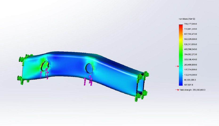
I went through 3.5 iterations over the past week on this design. Initially I was just throwing it together, but then when I realized how much force was really involved I decided to start running FEA and adjust the design so I could have a safety factor. Also, I was originally using scrap metal from around the shop, but the FEA was showing i just need more steel. So now the design is coming along with 5/8" steel plate, and will be available for open source if anyone is interested.