Project 5: Electronics Design
This week we were to learn an electronics design software such as the freeware and also commercial Eagle-CAD or Altium, or even the .cad format in the fab modules; we were tasked with learning how to design a circuit board. This week is a nice stepping stone from our first electronics project a few weeks back that taught us how to machine a pcb, but nothing more, and in the following couple weeks we will learn to actually program microcontrollers. This week was focused on designing a circuit board from scratch - that is design the schematic, layout the board and cut the copper.
Nearly six years ago I learned Eagle to make a power distribution board (much fancier than it sounds) while I was working at Makani Power, and unfortunately I have not had the time to use the program since then. So for a split second I thought I would go big and jump into Altium instead. I realized however that I should really become very proficient in the more accessible software - eagle. I chose not to use fab modules as I am not yet a strong programmer and I am currently more interested in visualizing the boards. It is unclear to me which method will ultimately be better for completing complex boards. (Making use of the autorouter in Eagle leaves one believing programmatic routing is not quite as creative as a human).
Motor Controller
I spent some time thinking about what electronic tool would be most useful to me right now; a micro-controller/motor driver combo seems the most applicable. It was a tough decision, as capacitive sensing is very interesting and could be used to make force or position sensors, as is assembling an IMU board. Nonetheless, it seemed that a simple DC motor driver would be directly applicable to my research needs, and could also be helpful when ever I get around to making the reacher project. The main issue is that microcontrollers and motor drivers are often available as breakout boards, but it seems nice to have them integrated into a single package. Also, it turns out it is faster for me to spend half a day learning and designing a board with the components located in the FabLab inventory than it is to order breakout boards online.
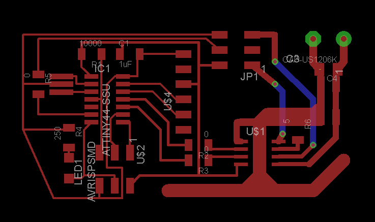
The system is as follows: I copied the layout of the hello world board (I initially tried to do the whole thing from scratch and realized I was having a bit of difficulty routing all of the traces and so I used that link above to get started) and then included the A4952 motor driver chip and inputs for a potentiometer or another three pin encoder type device. The motor driver datasheet gives some sample circuits that suggest some capacitor and resistor components to include alongside the chip. So I followed the instructions as much as seemed necessary. One note that complicated things. There is a pad under the chip that is for heat dissipation. The datasheet actually recommends running vias under this pad to distribute heat to other ground planes of the board. Not having plated vias seemed to me to not be very useful and it would be difficult to bridge the gap without leaving residue. So instead of vias I routed the ground plane a good ways out from underneath the chip. This extra copper acts like a heatsink to take the heat energy into contact with the ambient air. Also, the board is setup to take a secondary "analog" voltage source that is capable of higher power for running the motors. The motor side of the board has wider traces to allow more copper to carry more current to the motors.
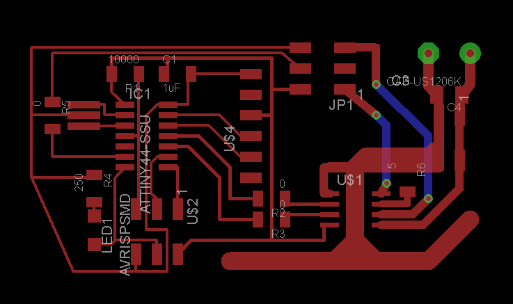
There were some tricks to get this board to work as a single sided board (I really did not want to spend the time to setup locating pins) although It would have been nice to shrink the size a bit more (that will come later, likely). The motor driver really wants to have a multilayer board, and it seems that the manufacturer even assumes you are using a 4 layer board with internal power planes. I originally had multiple LEDs for indicators to help me see that communications were working, but routing became difficult so I abandoned most of them. The two tricks I used was:
- I am making use of 0ohm resistors to jump over some digital traces to get potentiometer signals from the motor connector back over to the microcontroller.
- I cut vias and routed a bottom layer route (to satisfy Eagle) and I am soldering jumper wires across the top side to reach over the wide copper lines of the motor lines.
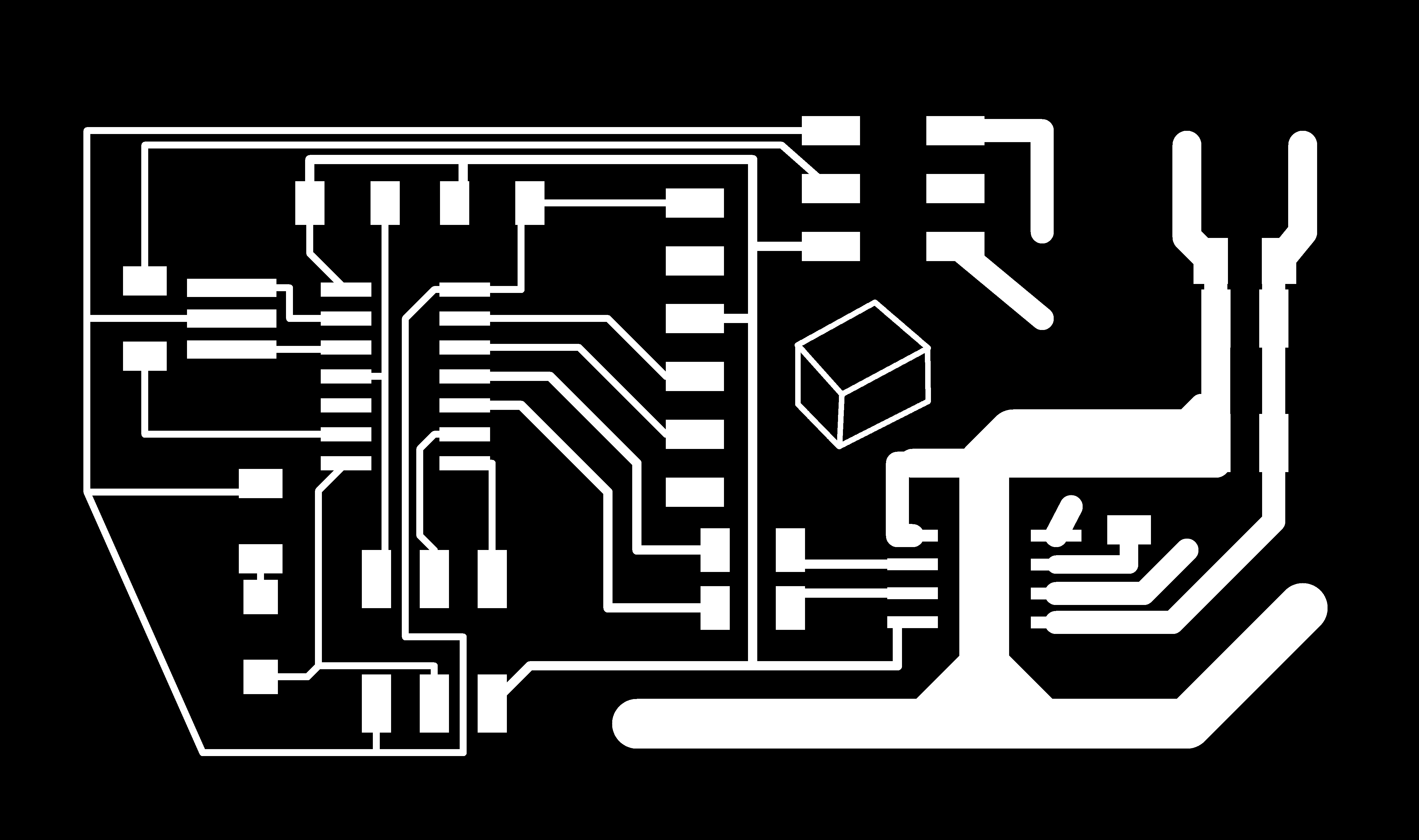
Exporting the files hung me up for a bit. The board png exports (welp we just had a Fire Alarm and a building evacuation (see below)) were showing up larger than the outline I had defined. It turns out that the image extents surround any layer on the board layout, regardless of if it is visible. The names of some of the components were extending beyond my board outlines. I "squashed" the components and was then able to move the names of components such that they didn't extend beyond the outline. This enabled me to reduce the outline to the dimensions I expected to see.

Important things to know about exporting:
- Export image at 2000dpi resolution, monochrome
- Traces should be white, everything else black (change the background color in Eagle to invert how these export. traces
- Holes should be black with everything else white. holes
- Outline should be all white with black on the edge of the border to be cut. board outline
The way the png to rml program works is that it looks for white/black edges. White is the desired feature while black is to be removed. See below for example images
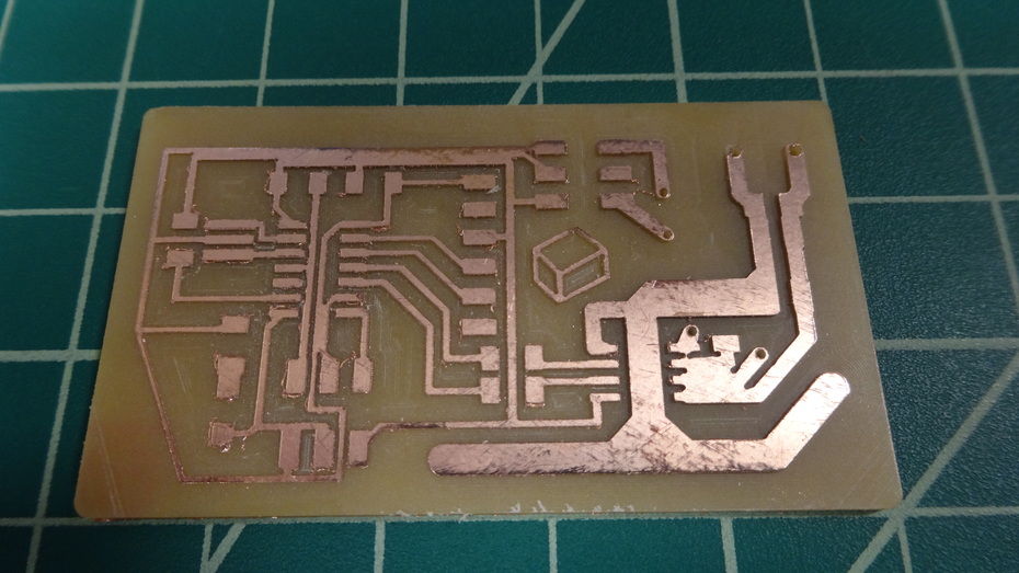
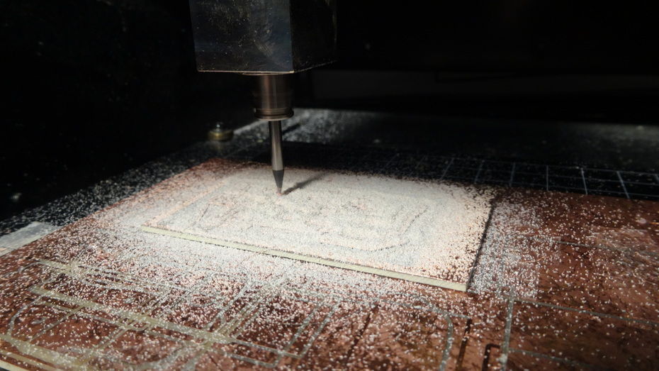
Looks like the spacing between the leads of the motor control board were too narrow and the path planner was not able to cut between the lines. So, I'll have to re-run the boards, or manually slice the traces. I updated the layout, but will not cut it tonight. Not after the fire-alarm, I lost a bit of time and I need to move on to other projects for the evening.