Project 7: Embedded Programming
The most basic level for this week is to get a premade program working on the circuit boards we designed and assembled. Then make a modification to the code to do something else. In order to make code the microcontroller understands we need to compile the C code into a .hex file using a driver library called avr-gcc that compiles our code. We then use a program called avrdude in conjunction with a piece of hardware called an In System Programmers (ISP) to flash (in the old days the EPROM memory could be wiped by flashing an intense UV light through a little window on the chip) and program the microcontroller. We can then use an FTDI cable to communicate between the microcontroller and our computer through a usb port.
This process can be done somewhat manually, or with a make file that combines multiple steps. Additionally, we could use the Arduino environment by loading a bootloader and then making use of the Arduino libraries to simplify programming, or if we're real hardcore we could write the Assembler code ourselves.
First I'll explain the simpler avr technique to load files to a microcontroller (uC) using make files, then the more indepth technique, and finally the arduino method. First though we need to verify we have the correct drivers and software for everything to work. As a reference I used the Fab Academy instructions and the High-Low Tech:
For windows:- Install WinAVR if you're on windows: this includes the avr-gcc, avr-libc, and all those goodies.
- Install FabISP firmware. This is firmware for the FabISP programmer as well as drivers for windows.
- Install the 64-bit windows drivers for USBTinyISP from Mighty Ohm, assuming you are running a modern 64bit system (less than 4 years old pc). Follow the instructions at the bottom of the page on the link above to install 64bit drivers for the FabISP to be recognized in windows. This will let the FabISP showup and be accessible by the WinAVR stuff.
- Get the FTDI drivers so you can communicate through usb/serial between computer and uC.
- I think that's it! sheesh!
Simpler avr method to program the uC using a "makefile"
Compile the code - convert the (filename).c files (C-language that humans can read) into the (filename).hex files (Hex language that microcontrollers can read):
make -f hello.ftdi.echo.c.make- Connect the FabISP programmer to the uC board. Note the uC must also be powered with 5V (this can be done with the FTDI cable if desired or another power supply):
- Program the fuses (generally only necessary the first time firmware is loaded to the microcontroller).
make -f hello.ftdi.44.echo.c.make program-usbtiny-fuses - Send the .hex file to the microcontroller using the FabISP:
make -f hello.ftdi.44.echo.c.make program-usbtiny
A more indepth look at the avr process
To run the standard code for the class, looking below replace (filename) with hello.ftdi.44.echo
- Compile the code, two steps
- Compile an assembler file:
avr-gcc -mmcu=attiny44 -o (filename).out (filename).c
- Compile a hex file from the assembler file:
avr-objcopy -O ihex (filename).out (filename).hex
- Compile an assembler file:
- Program the Fuses on the microcontroller, there are three of them although we are only needing to program the low fuse (only need to do it the first time the uC is programmed) .
Fuse Explanation, Fuse Calculatoravrdude -p t44 -P usb -c usbtiny -U lfuse:w:0x5E:m
- Program the microcontroller (update the firmware) with your code by sending the .hex file to the microcontroller through the programmer FabISP.
avrdude -p t44 -c usbtiny -U flash:w:(filename).hex
See if hello.ftdi.44.echo is working
- Open a terminal program, this can be done with Neil's lightweight Python terminal program, or through another terminal program such as PuTTy or windows terminal. If you'd like to use Neil's program, which is quite nice, you need to also have the following.
- Install Python 2.7 (I prefer this over 3.x because it still seems to have better support)
- General reference here: Unofficial Windows binaries for Python Extensions, all the 64bit Python stuff you normally can't find.
- Install PySerial (for serial communication)
- To use type the following at the command prompt:
python term.py com6 115200Where com6 would be replaced with whatever your serial port shows up as on your system. Note also, that it maybe necessary to adjust the communication speed parameters in the windows device manager to operate at the 115200 baud rate specified.
- Open a virtual serial port connection. This is what the FTDI chip does, it simulates a serial port through a USB port. In windows you can go to the Device Manager and see under the Ports section a USB Serial Port (COM?). This is the communications port to specify in the terminal program.
- Once connected, the program will echo keytrokes. so type a key. Hopefully it works
Issues
I ended up being successful with the project despite an initial issue with communication frequency. I had python already installed on my computer and when I ran the the term.py program I got gibberish on thhe screen. What I realized though was that the gibberish was actually doing the echo as it should, it just was not displaying the correct information. So that meant the microcontroller was infact programmed, but the communication lines were not synchronized. So, looking into how to specify the communication rates in the AVR code I saw the following lines:
#define bit_delay_time 8.5 // bit delay for 115200 with overhead

        #define bit_delay() _delay_us(bit_delay_time) // RS232 bit delay
The bit_delay_time is used to specify the delay time in communications channel to synchronize the serial communication. So doubled checked how many microseconds of delay should happen and 1/115200 = 8.68*10^-6, or 8.68 microseconds. So I changed the value to:
#define bit_delay_time 8.68 // bit delay for 115200 with overhead
and then communication seemed to work perfectly.
I got the echo working, and I was able to make the LED blink in both AVR and Arduino and using the makefile and not using the makefile. The files are here: test.c, test.c.make
Arduino
I made use of the highlowtech folks again with their Attiny as an arduino tutorial. I also tried loading the Arduino bootloader onto the board and running an arduino code on it. This was successful when selecting the USBTinyISP programmer. However the serial communcation was not working correctly. I think I need to do the serial through software on this chip, so I'll need to get into that...later. I decided to jump back to playing with the avr stuff directly.
Motor Controller with 9V supply
I wanted a lightweight motor control board that could have a simple potentiometer position feedback loop or potentially a capacitive input device. I'm realizing now, I left one pin unused and I could have made use of that to allow a quadrature encoder input as well. Ohwell, next time. The pain point is that it is neat to have a very low cost motor driver for tiny motors, and including a position feedback loop allows for a precision position control system. Actually, just thinking about it now, that extra pin could also be used to put a tachometer on the output in combination with the potentiometer. This would allow a cleaner velocity measurement for better PD control. The reason to use a DC motor instead of stepper motor is that a DC motor can potentially generate more torque than a stepper by dumping more current into the motor. Stepper motors locate into stable magnetic orientations, that is they have holding torque but not really moving torque. Microstepping overcomes the holding torque of the motor to hold in intermediate positions between the motors natural stable positions. So the maximum torque possible is limited by the holding torque of the motor. A DC motor can actually sink as much current as the wire enamel can withstand heating. So, it is technically possible to provide sufficient cooling and overpower a DC motor. Of course there are issues with regards to inside our outside coils and how well they can cooled. But it also means that for short bursts it is possible to generate more current(torque)/size than a stepper motor. Using a cheap DC motor and a cheap encoder is likely possible to outperform a stepper motor in torque/weight generation as well as smoothness of the torque profile.
Looking at the assemblers I will be designing for my research, it makes sense for me to have a lightweight motor controller that is based around a DC motor, such that I can be sure to use motors that can hold themselves up and generate torque spikes as necessary.
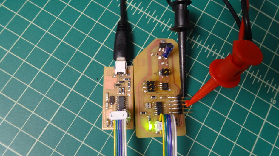
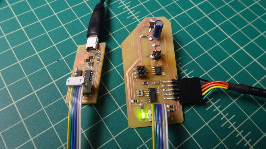
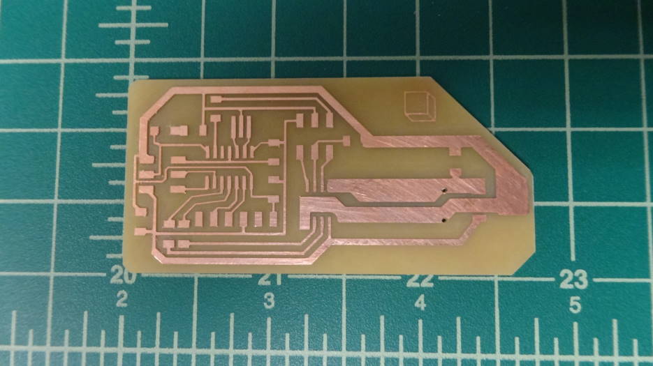
I basically took the standard hello.echo board and added an LED for diagnostics, an A4952 Full-bridge PWM motor driver, a LM2940IMP voltage regulator to regulate 9V down to 5V, and some extra pins for i/o with the motor and potentiometer. The files can be downloaded here, and the partslist here.
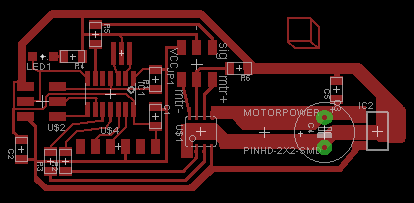
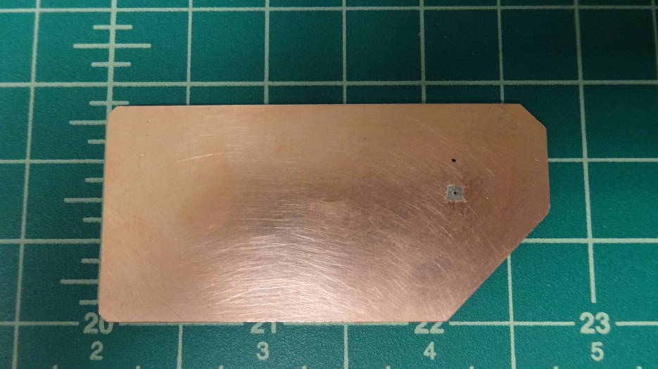
An error I made was that the large copper pours for the input current handling is actually really difficult to solder due to its heat conduction, and it was difficult to get heat to the pin placement. Additionally, I did thicken up the traces to the motor output pins which would have been helpful for current carrying capacity. I used a through hole electrolytic capacitor to provide a little more current capacity to the system in the event the motor current draw drains the current of the system and sags the voltage of the system. Because of this and the double sided board I had to cut out an area around the positive lead of the capacitor. I made a point of soldering the negative to the bottom side to give myself a large ground plane that may be useful when i try to play with capacitive sensing in a couple weeks.
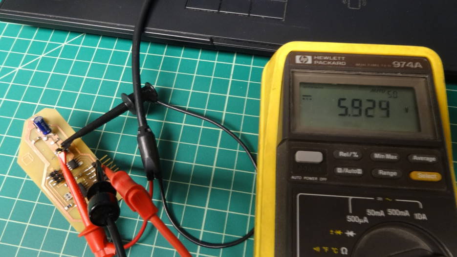
I made a point of going around and checking each of the subsystems to verify they were working. At 9V input from a power supply the voltage regulator was able to keep power at about 5.9V, a little higher than I would have liked, but technically within the operating range of the ATiny44 (6V).
I have not yet got to testing the motor driver