Welcome to Mohit's first dig at making REAL stuff
Final Project
Main Idea
The main idea of the project was to build a sound measuring bar. This bar would light up a number of "cubes" depending upon the amplitude of sound
giving users active feedback on how loud they're speaking. This is especially useful in classroom environment where everyone needs to speak loud
enough for everyone else's benefit. Instead of the professor reminding students to be loud, students can get active feedback from lighted cubes.
Tool used
1. Solidworks for 3D designing enclosures for light source (in this case, a bunch of LEDs)
2. Eagle to design electronic circuits
3. Modela to print circuit boards
4. Laser cutter to print press-fitting enclosures
5. Arduino for application programming
Step by Step progress
First, I wanted to create a circuit that could interface between a microphone and LEDs on a small circuit board. The idea was to capture signal from
a microphone, measure it and use that value to light up LEDs. The biggest challenge I faced was in getting the microphone circuit to work. It took
me more than two weeks to troubleshoot what was going wrong.
My first few trials were with Neil's hello board shown below:
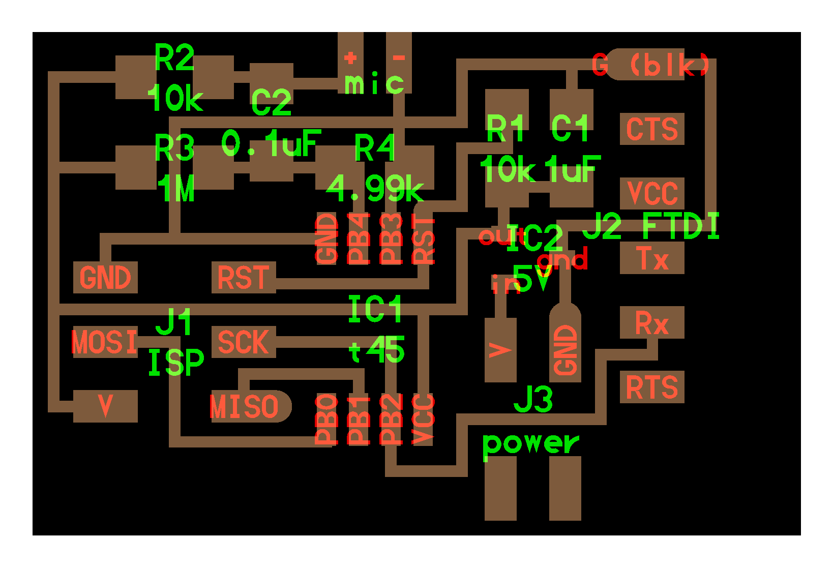
While this board is functional, I measured signal from the microphone on a serial port but the values were very low (between 1-10) and did not change
even if I spoke into the microphone. Even if I screamed really hard, the values changed only by a little bit. It almost seemed like noise and I could not use
those values to logically light up LEDs. This could have been due to the old electret microphones that we had in inventory. I did not get a chance to
test the circuit with new microphones.
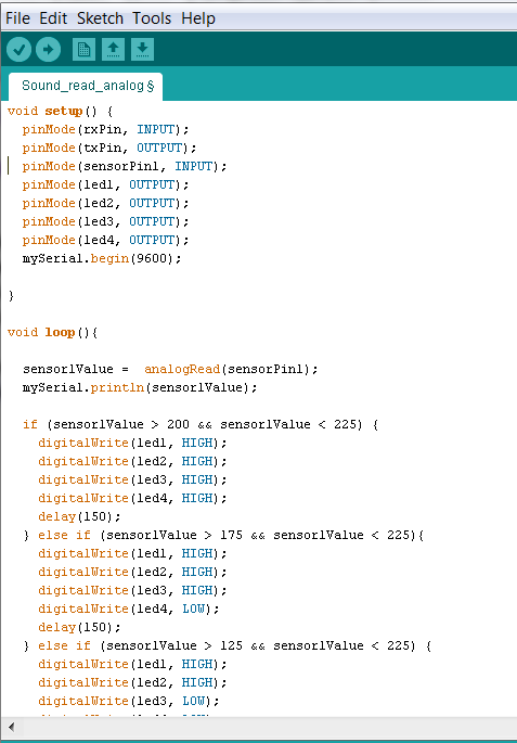
Given below is the Ardunio code for reading signal from a microphone:
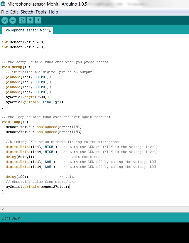
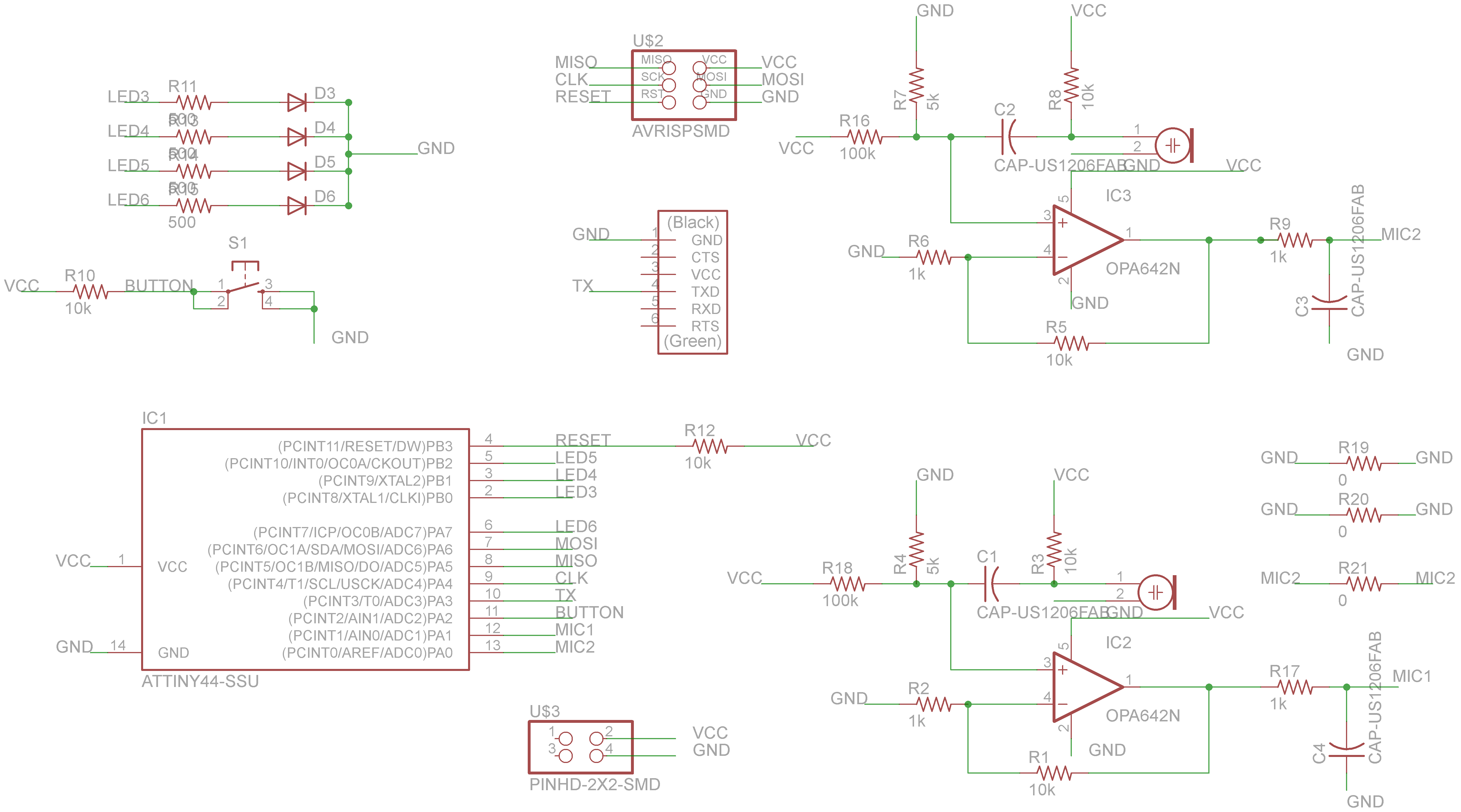
Then, one of our very helpful TAs, Raj Nair suggested that I used ab op-amp to amplify the signal from the microphone. I created a new circuit with op-amps
and two amplifiers (at that point I wanted to average the signal from the two microphones). The schematic and components are given below:
Schematic
Board
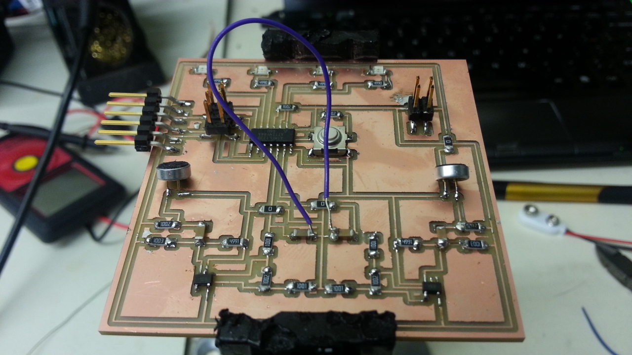
The gain from an op-amp depends upon the resistances used with it. If you look at my eagle schematic you will see that I used a gain of 10x (Ratio
R5/R6). Normally you might want to play with gains to see when the signal is amplified enough to read by using a potentiometer in place of one of the
resistances or manually change resistance values (which is what I did since I could not find a potentiometer).
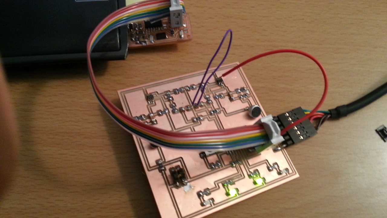
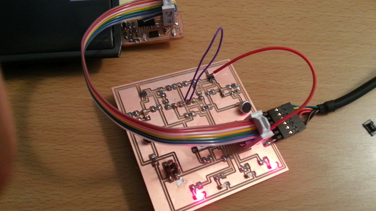
However, I still could not get a measurable signal from the microphone. It always showed 1024 for some reason and I could not figure out the source of error. Again
I could not use microphone signal to logically light up LEDs.
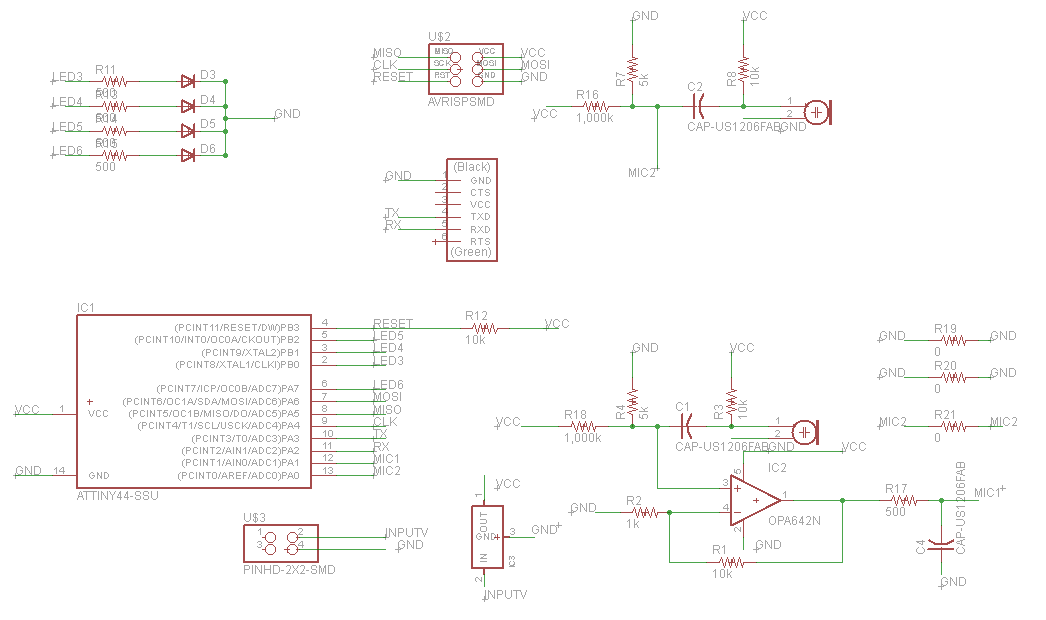
Next step in troubleshooting was to create another circuit board with two microphones - one with op-amp and one without an op-amp. The idea was to compare
the difference in signal received from the two microphones.
The schematic and components are given below:
Schematic
Components
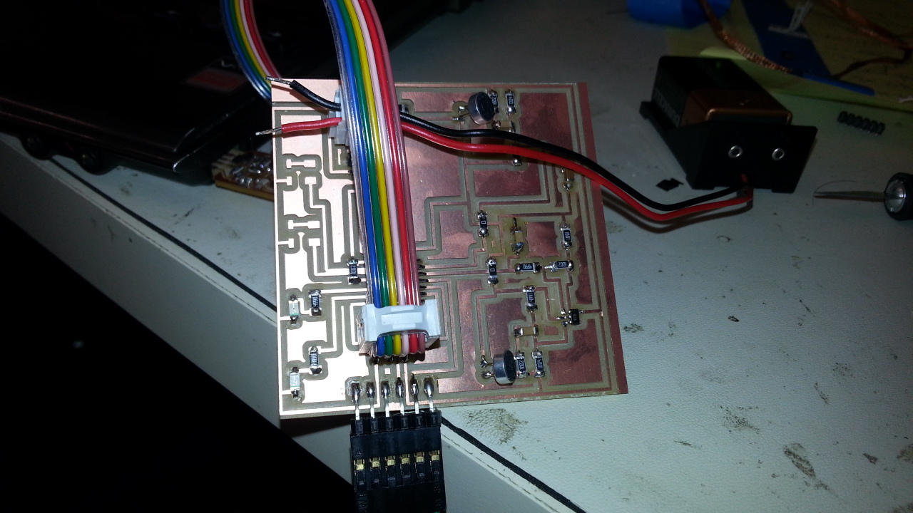
This was interesting. While the signal from the microphone was very low and did not change, the microphone with the op-amp gave observable signal and I was
finally able to link the output of the microphone to logically lighting up LEDs. WIN!!
VIDEO of LEDs working with input from microphone
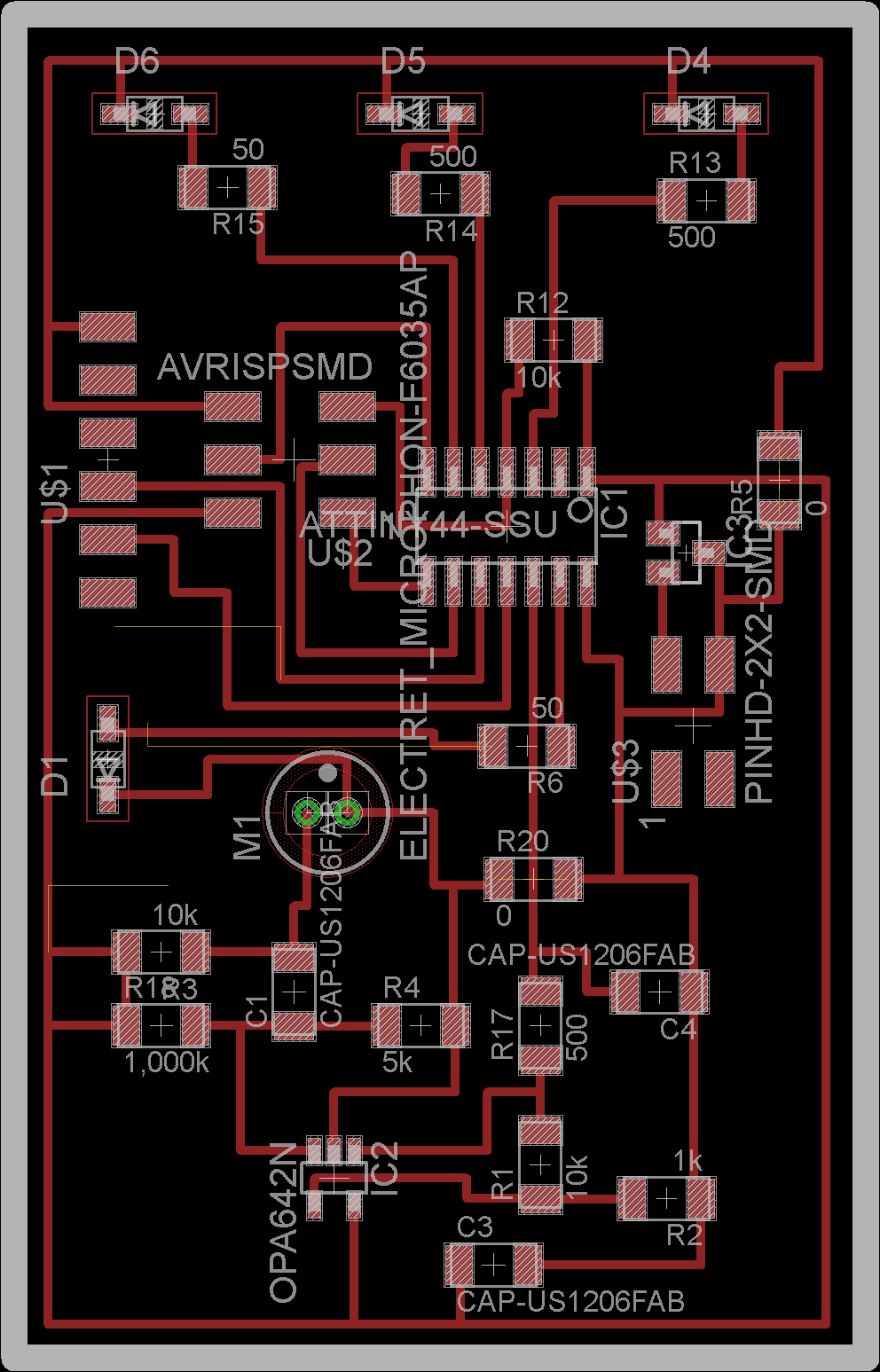
Next I re-created the main board and removed one of the two microphones. The new schematic and board layout is given below:
Schematic
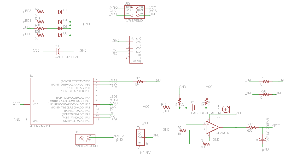
Board
Video of working circuit
Now that the new circuit also worked for multiple LEDs, the next step was to replace each LED with a separate board of multiple LEDs so that a group of
LEDs would act as one bright light. I thought this would be easy but it became very very tricky since I was not able to transfer signal from a microphone on one board to another board. Everytime I tried to send something
using Arduino's examples (look at TinyWireM, Wire classes), either the data did not go through or it seemed to get garbled up.
I created a new board and I wanted to try the big 12V LEDs (shown below). However I could not make the slave circuit work with regular LEDs. I did not get
a chance to include 12V LEDs in the circuit. I suspect the voltage might not have been enough to drive those large LEDs anyway. However, the large 12V LEDs
lit up (very dim though) when I replaced one of the regular LEDs on the main circuit with a large one.
The slave board with lights was supposed to have the following structure:
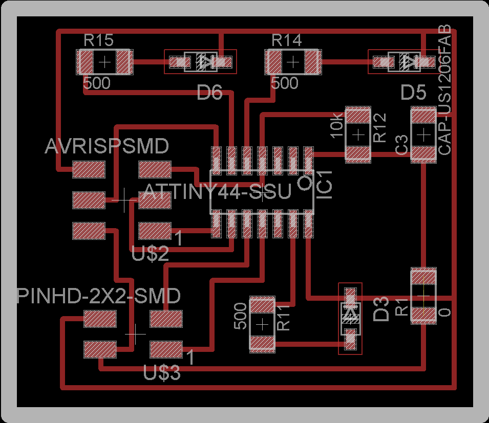
Note that I could not get it to work on a network with the main node so I did not use the above circuit. I did spend a lot of time trying to get it work.
I got some useful links from Rob Hemsley to reach about networking programming in arduino.
Useful links for networking using Arduino (I got these links from Rob Hemsley):
www.arduino.cc/en/Reference/Wire
tronixstuff.com/2010/10/20/tutorial-arduino-and-the-i2c-bus/
Implementation for ATTINY85
Note that the same code will not work for both ATTINY85 and ATTINY44. I was using ATTINY44 - that is where I got stuck.
I would have modified Neil's code from networking week to work with my circuit but I was pressed for time so I had to take a relatively easy way out.
I connected a board of LEDs in parallel with the main LED on the main board. Essentially, it was equivalent to extending a board on to other boards.
Given below is my initial implementation of the LED Array board:
Schematic
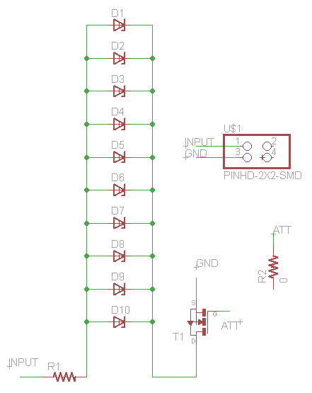
Board
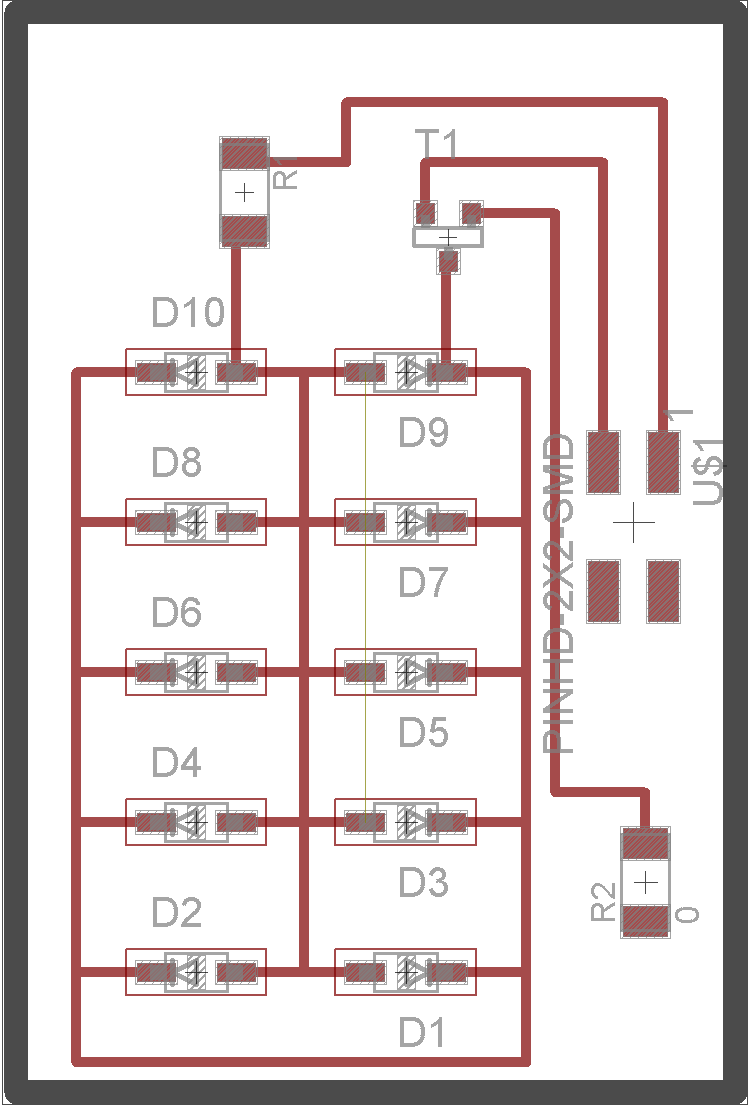
Initially I did not have an N mosfet on the board because of which all LEDs are lighting up based on Voltage from the main board which was very low
(around 2V). I wanted to power each board of LED arrays with a higher voltage. The N mosfet allowed me to do just that - the power from the 9V battery was
connected to all boards (main board and LED array board) and while it was regulated down to 5V using a voltage regulator (necessary to avoid frying of ATTINY
chips), others received full 9V voltage.
Video of working circuit
Next I tested the circuit with one LED array board (connected in parallel to first LED on the main board). The video below shows that all the LEDs on
the new board do not light up. It took me a while to understand but after discussing a bit with Kristin we concluded that all LEDs light up only if they are of
the same colour. This is because my LED array circuit has a common resistor for all LEDs. Since different colour LEDs are slightly different, only LEDs with
lower resistance light up. So I decided to put only colour of LEDs per board.
Video of working LED array (1) circuit
The next step was to create enclosures for each LED array and the main board. I used Solidworks to design these enclosure and cut them on acrylic
sheets using a laser cutter. It was a little difficult to get a precise fit since there was some margin of error on the laser cutter. I had to iterate
multiple times before I got decent press fitting enclosures.
I used three types of objects that were used to create enclosures for circuit boards. Links given below:
Part 1
Part 2
Part 3
The final setup with three enclosures and relevant circuits looked like this:
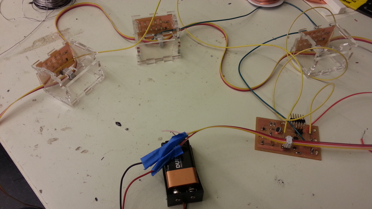
Video of final working circuit
A major problem I faced after adding arrays of LEDs on separate boards was that once a board of LEDs lighted up, it would not go back to 0 state and
it also forced the parent LED on the board to stay on as well. I investigated this by looking at data on serial port and I observed that as soon as one of
the LED array boards lighted up the signal received from microphone became very high. Hence all LEDs were above their threshold to light up all the time and
so all of them stayed in on state.
Essentially some kind of noise hit the circuit that prevented accurate calculation. To fix this, I changed the code and ignored all data where values
was above a certain threshold. This way the LEDs did not stay on and the board functioned better. The Arduino code is given below:
Arduino code
