Welcome to Mohit's first dig at making REAL stuff
Week 10: Output devices
For the tenth week, we were asked to learn to use an output device (e.g. LCDs, motors, LEDs etc). My idea was to use sound input and the intensity of
the sound would drive the number of LEDs that light up.
My board looked like this:
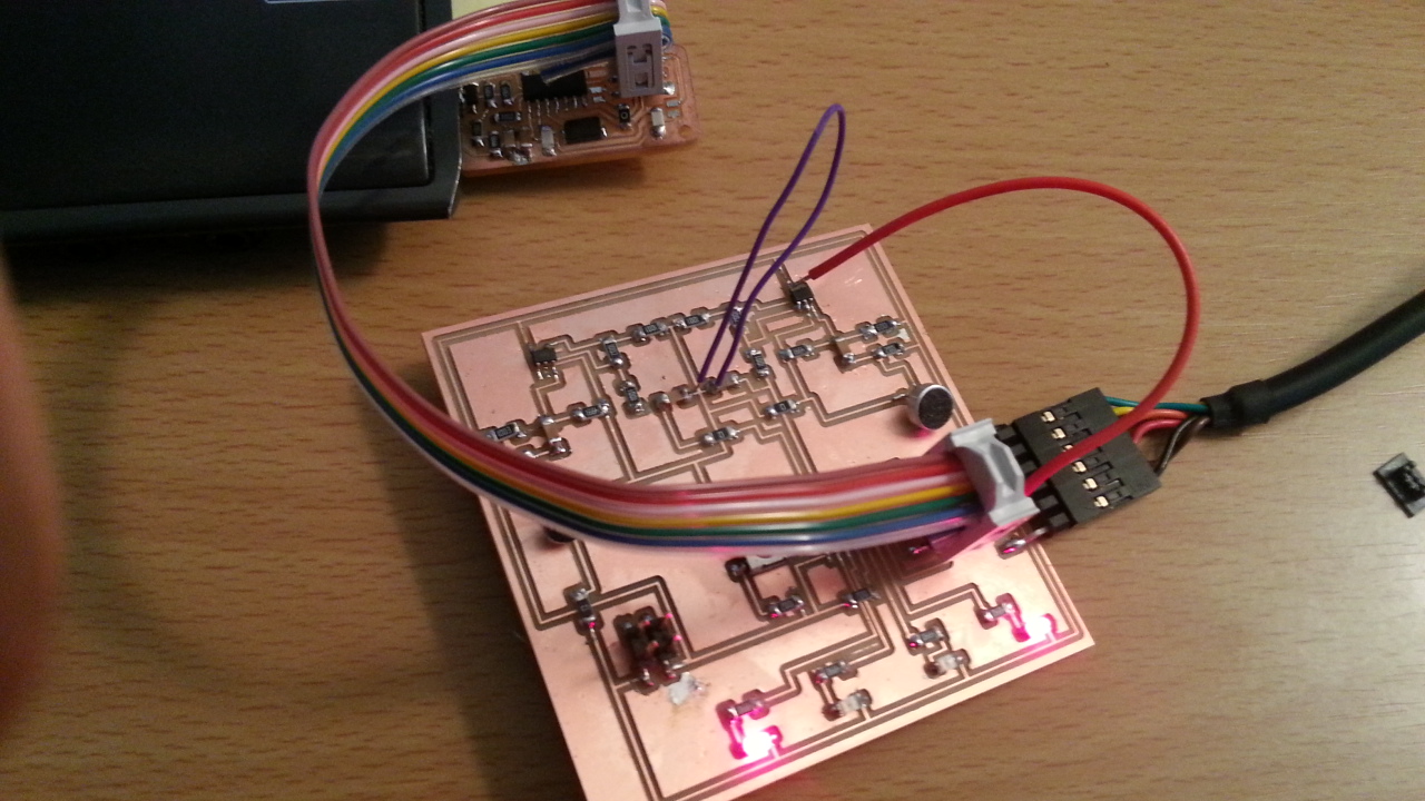
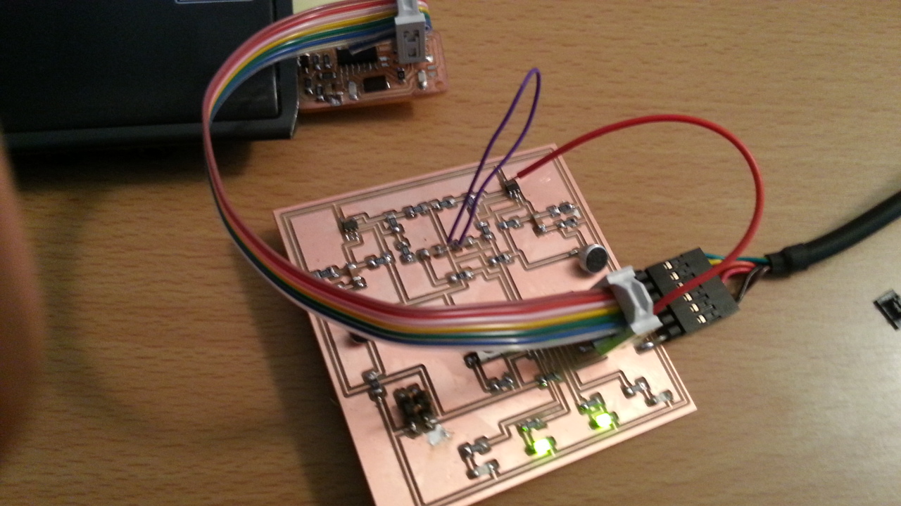
Note that you can see different LEDs light up in the two pictures. I played for a long time with LEDs and tried to do different things with them -
such as changing interval times for blinking or making the blinking pattern more random.
My next step was to measure the input from the microphones (I had two) and use those numbers to decide the number of LEDs to light up. For some reason
the level observed from the microphone did not change much even if I made noise around the microphone. I change the amplification factor on the op-amp
from 2 times to 11 times but nothing changed. I suspected something was wrong with the circuit - most likely with the resistance and capacitance values.
To vary resistance I need to replace the standard resistance with a potentiometer. We did not have a potentiometer in IDC so I will pick it up from another
lab and put it in my circuit.
While I was doing all this, I realized I had programmed my microprocessor via Arduino incorrectly using the external crystal option. Initially the LEDs
worked but they stopped working after a while and I could not reprogram the circuit. It is important to note that once the ATTINY44 chip is programmed
to use an external crystal as clock, it can not go back to using the internal clock.
So I had to replace the crystal on my circuit. I also tried to measure the voltage across input and one of my mics and in that process I ruined the circuit
since the mic came off and along with it some part of the circuit (copper line) also came off! I need to re-print my board, fix errors and try the whole
thing again.
Another learning was that it is useful to use a voltage regulator. I did not use one and I was planning to use an external battery as a source of power.
The external batteries were all 9V and anything above 5-6V can fry the micro-controller. So I ended up connected VCC to the FTDI cable to use USB power.
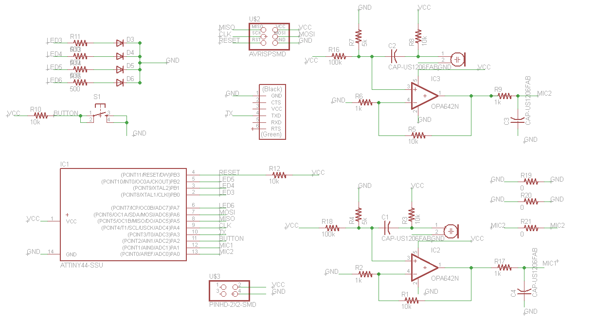
My eagle schematic is given below:
Video of blinking LEDs