863.13 // taylor
electronics design
This week started up by designing a PCB for an ATTiny44 chip in Eagle. The board needed to have 1 led and 1 switch. I decided to put two leds and a switch instead. Eagle went pretty smoothly. The main things I learned were :
- - use the tool in the menu bar to check for errors Tools > Errors
- - export high res pngs or else the fab software won't be able to read it.
- - make sure your traces are >= .03"
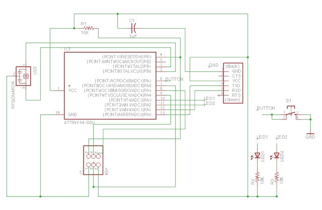

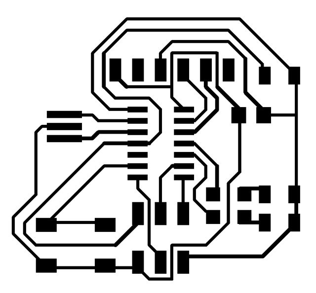

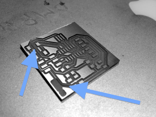
Below are some images of things that went wrong.

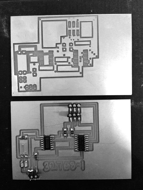
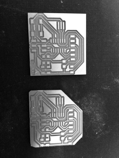
On the left below is my final board, on the right is my final board with a simple program running. I used the hi-lo tech attiny tutorial to use the AVR MKII to program my board. The program reads the input from a button press to toggle which led goes on.
	int led11 = 3;
int led10 = 2;
int switchIn = 7;

int activeLED = led11;

void setup() {

  pinMode(led11, OUTPUT);
  pinMode(led10, OUTPUT);
  pinMode(switchIn, INPUT);
  digitalWrite(switchIn, HIGH);
  digitalWrite(led11, LOW);
  digitalWrite(led10, LOW);
}

void loop() {

  int buttonState = digitalRead(switchIn);

    if(buttonState)
    {
      digitalWrite(led11,HIGH);
      digitalWrite(led10,LOW);
    }
    else
    {
      digitalWrite(led11,LOW);
      digitalWrite(led10,HIGH);
    }

}


Straight into LTSpice extra + unresolved.
The first thing that I decided to do this week was start playing around with LTSpice. I got really excited by it after the great tutorial Brian ran. One of the reasons I wanted to try out LTSpice was for a piece that I am working on that will show how a quartz crystal oscillator works in a wristwatch. These components are in so many of our devices, but few people, including me really understand how they work.
One of my first steps in making this piece was to learn about how a crystal is made to oscillate, and then how that oscillation is divided into a time signal that can interface with the mechanics of a watch. Once I did this (I can go into this somewhere else because I learned some interesting stuff, but it's not that relevant here), I designed a circuit to try this out for myself. I based this circuit off of this circuit. I wanted to pair this down even more so that I could model the bare minimum required to make a crystal resonate.
I thought this would be super straight forward, but it turns out that they don't really give you an 'off the shelf' crystal in LTSpice. Well they kind of do, but you can't just specify a frequency and voila it works. Instead, you have to build a resonator out of resistor, inductor, capacitor circuit. So you specify all of those values. I plugged these into an online calculator and got close to my desired 32,768Hz, which is the frequency used in a watch crystal.


This is something I would still love to get working. This could be a very powerful tool, but I didn't have time to dig much further this week.