From Altium to the Modela
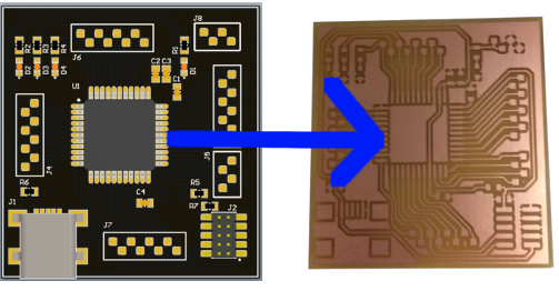
The “PCB Production” assignment was simple: here are the PNG, use them to mill your PCB. Now, for a custom design, how do
we generate these files? In this tutorial I’ll explain to you how to close the loop from Altium to the Modela.
Software needed:
- Altium
- Fab Module
- PDF Creator
- GIMP
- IRFanView
Design requirements:
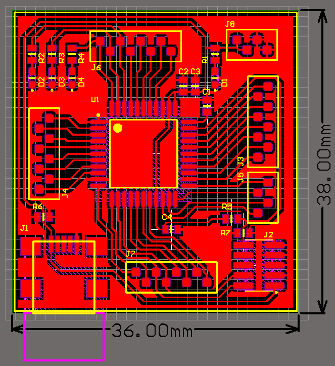
I used a 10 mils endmill to do this project. This is the smallest that we have in stock. If you can, use the 1/64th (~15mils) I needed the
10 mils for my TQFP package. Yes, I could have modified my pads… but I wanted to see the limits of the machine.
I initially used 10/10mils trace/space and 10 mils polygon clearance. The Modela skipped some sections. I assume it’s coming from
arc and line approximations, some lines might have been a hair smaller than 10 mils (Altium is horrible at catching its own errors).
To make it work, I designed everything with a 10/10 rule and a 15mils polygon clearance, then, at the last step, I changed all my
traces to 9 mils. You can also start with 9/11 from the beginning, it’s up to you. TLDR: keep your spacing bigger than your endmill diameter
As for the Outline (Mechanical 15), I used a 1 mil wide line.
Now that you have a valid PCB design, here’s how to export it:
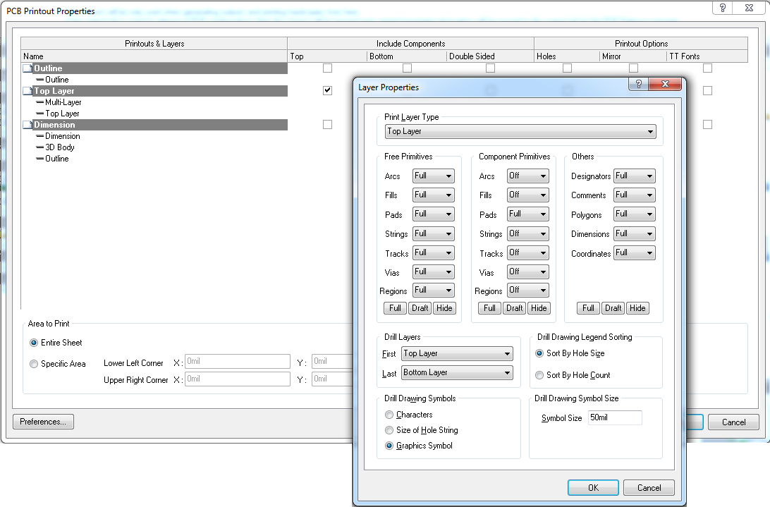
- In the Altium Output Job file, Add "Final Artwork Prints" to Fabrication Outputs
- Rename it “Modela PDF”. Double click on it and modify it to get your Top Layer like on this screenshot:
- Click on the “Modela PDF” line, then File => Page setup... Change the Scale Mode to Scaled Print, Scale = 1.0. Set Colors to Mono
- If you do a print preview, you should see your PCB in the middle of a Letter page (assuming it's a small board). If it doesn't seem to scale, something's wrong.
- Set PDFCreator as your printer. It has the ability to print in PNG.
- Click Print, the PDFCreator menu will open. The first time you do this, click on Options and under Formats => PNG set the resolution to a high number and the colors to Black and White. I used 2000 DPI. Exit the Option menu.
- Save as type PNG
- Ok, you now have a high quality PNG. It contains a single layer. In my case I need 2 layers (Top and Outline). By changing the order of files in the Artwork you determine what's going to be printed (right click => Move Up/Down)
- Now that you have all your layers in PNG files, fire up GIMP, File => Open as layers... select all your layers. Opening multiple file as layers allow you to crop them to the same dimensions without loosing alignment.
- Crop to a size slightly bigger than your artwork
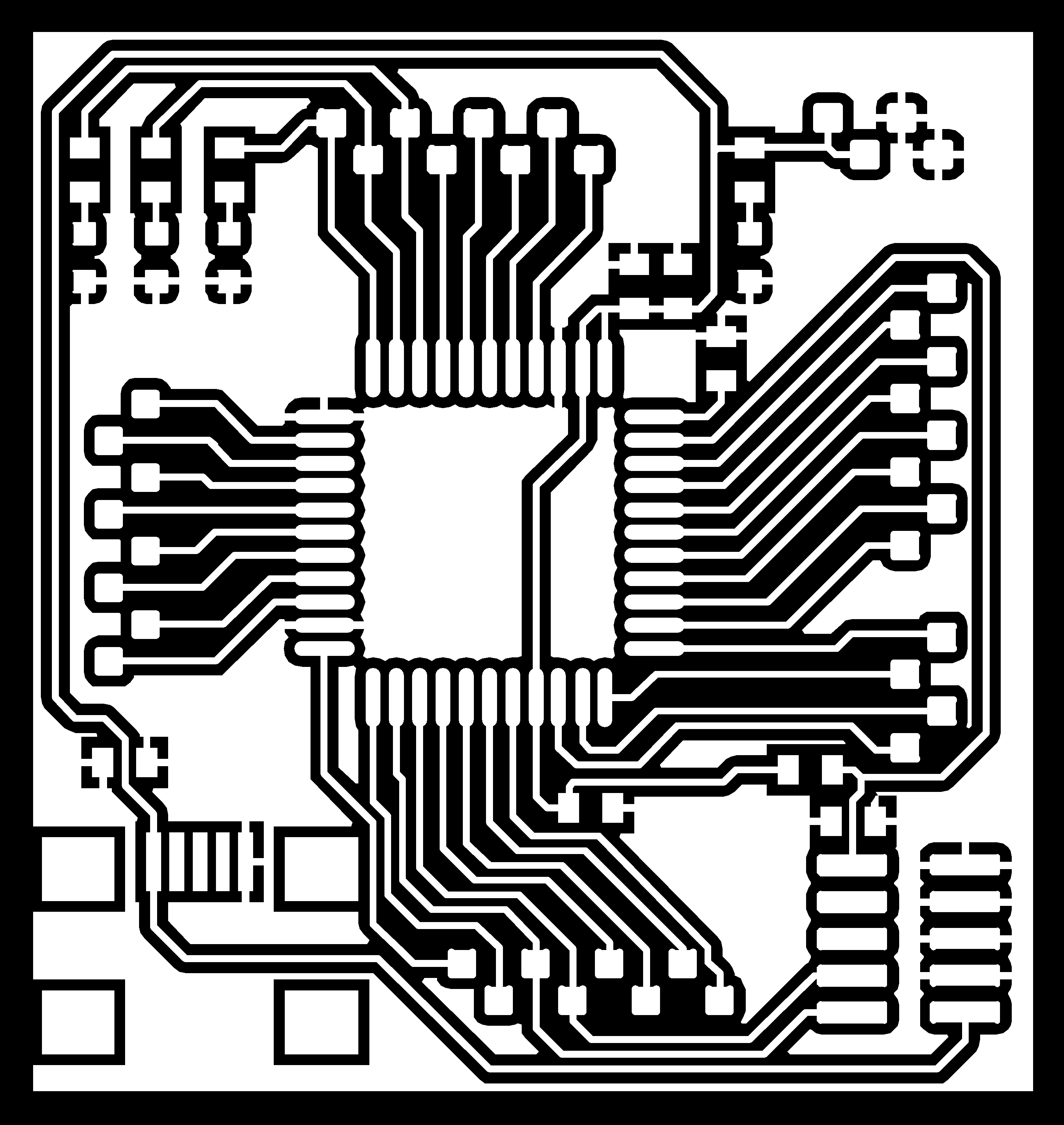
- You want the traces to be white. Colors => Invert will do the trick. For the Outline, you want a black outline. You need to fill the space with Black. Make sure it’s thick enough, otherwise it won’t cut. See pictures.
- You can now export your files as PNG (do them one by one by toggling the visible layer). I kept all the default settings.
- This step is optional; you can get the same information from the Fab Module. But if you want to feel safer: open one file in IRFanView and hit the ‘I’ key. It will display lots of useful information. Look for the resolution and the print size. For whatever reason, if your file are not at the resolution you want (2000 DPI in my case) you can edit them with IRFanview. It will also tell you the physical (print) size of the files.
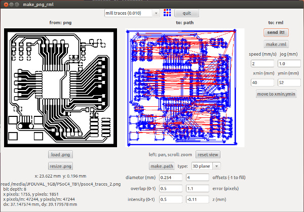
- Ready to mill!

Setting used:
Speed 2mm/s, jog 1.0mm, offset = 4, z = -0.12mm, overlap = 0.5, intensity = 0.5.
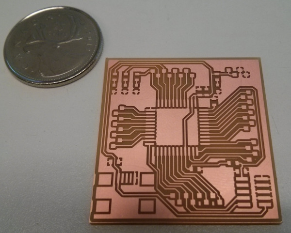
Milling this small PCB took 40 minutes but the results are awesome!
Feel free to contact me at jfduval (at) mit (dot) edu if you have questions or comments!