Week 7: Programming a Rainbow Soup
This week, our task was to learn how to load code on to the ATtiny44A that is on the board we designed in week 5. We do this by using the FabISP that we made in week 2, so having done both those correctly is somewhat of a prerequisite, although you can always borrow someone else’s FabISP (or even an AVRISP).
The code referenced below is available in Makefile and rainbow.c.
Setting up tools
I usually use Linux for most of my hacking, but my portable computer is a Surface Pro 2 that I use for taking handwritten notes and general office productivity features that aren’t available in Linux. It runs Windows 8.1, and because it’s the computer I always bring to the lab, I decided to try out the tools for Windows that were mentioned in class. As I understand, if you want to use Windows, you have two choices:
-
Atmel Studio, an integrated IDE (currently based on Visual Studio 2010) that allows you to compile code and program chips all in one piece of software.
-
WinAVR, which contains
avr-gccfor compilation,avrdudefor programming, and some other tools which allow you to accomplish the same things from the commandline.
I spent a couple of hours trying to get Atmel Studio to work. It’s great for writing and compiling code using the capabilities of Visual Studio, but not so easy to actually get the programming working. The software that comes with it only supports the commercial AVRISP mkii for programming, and the FabISP is a homemade device that it knows nothing about what to do with.
The workaround for is to set up Atmel Studio to program with avrdude instead of the built-in drivers. If you’re going to to this route, you may find the following search helpful:
Without this, Atmel Studio just seems like a glorified interface to a compiler, so I decided to skip jumping through these hoops and go back to my commandline roots.
If you’re wondering about the query above, it’s worth noting that the FabISP is essentially a copy of the USBtinyISP. Regardless of what development and compilation environment you end up using, you will have to download the drivers for Windows. (Drivers aren’t needed for Mac OS X or Linux.) To install these drivers, you have to find the FabISP in your Device Manager:
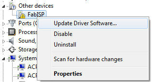
Then click Update Drivers, and browse to the files you
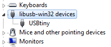
downloaded. After successful installation, your device will show up as
a USBtinyISP:
Next, install a compiler and uploader for your code. If you decide to go with WinAVR, as I did, you’ll find that it’s pretty self-contained and sets up all the necessary tools to be available from the commandline. If you start writing more complicated code, you may find the simulation and debugging tools of Atmel Studio more worth the effort to set it up.
Implementing a Rainbow in Software
In this post, I’ll be getting the RGB LED on my board to display a rainbow of colors. The code for this is relatively advanced for first-timers, but should be understandable for anyone with programming experience.
Writing C code
This section will go over how to implement independent 3-pin software
PWM to make an RGB LED display different colors. If you’re just
interested in programming, skip down to the section about
Makefiles. I’ll go over the code in different sections.
Includes and Macro Definitions
#define F_CPU 20000000    // AVR clock frequency in Hz, used by util/delay.h
#include <avr/io.h>
#include <util/delay.h>

#define output(directions,pin) (directions |= pin) // set port direction for output
#define set(port,pin) (port |= pin) // set port pin
#define clear(port,pin) (port &= (~pin)) // clear port pin
#define pin_test(pins,pin) (pins & pin) // test for port pin
#define bit_test(byte,bit) (byte & (1 << bit)) // test for bit set

#define led_port PORTA
#define led_toggle PINA // Useful for toggling on/off without tracking existing value
#define led_direction DDRA
#define led_red (1 << PA3)
#define led_green (1 << PA2)
#define led_blue (1 << PA7)
The first section is very similar to the files for other examples in
the class. The #include lines which pull in libraries that provide
helpful programming macros and functions. The #define lines are
C macros which are essentially a search-and-replace done by the
preprocessor before the code is compiled. Most importantly are the
pins that will be used to drive the LEDs: red is on PA3, green is on
PA2, and blue is on PA7. On my board, these are in line with 1k,
1k, and 499 ohm resistors, respectively (the blue LED requires more
power to reach a similar brightness to the red and green).
One note of interest is the PINA port, which is generally used to
read inputs. However, it can be written to to toggle the state of an
output, as explained in this paragraph in the datasheet:
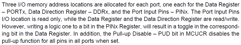
This can be useful to switch something on and off without having to track its current state, which can be helpful.
Color Table
// The colors that we will cycle through, with linear interpolation. These are
// somewhat like RGB colors, but not quite, as they scale brightness for PWM.
// {127, 0, 0} is not a dark red; it's a dim red. The following values were
// obtained through trial-and-error  for (1k, 1k, 499) resistors on (R, G, B).
const int COLORS[][3] = {
    { 200, 0, 0 }, // red
    { 120, 45, 0 }, // orange
    { 100, 75, 0 }, // yellow
    { 0, 150, 0 }, // green
    { 0, 0, 255 }, // blue
    { 100, 0, 180 } // violet
};

#define NCOLORS (sizeof(COLORS) / sizeof(COLORS[0]))
#define INTERP_BITS 6
#define INTERP_STEPS (1 << INTERP_BITS)
Next, I define a fixed table of colors that will be cycled through. Each color is represented by a 3-tuple of values representing the 8-bit PWM duty cycle for each LED. As noted in the comment above, we’d like to think of them as RGB values, but they aren’t really. This is because we have to dim the overall brightness when several LEDs are on at the same time, and the LEDs have different brightnesses at full power. I arrived at the above values through experimentation on my board, in an attempt to get a rainbow of approximately constant intensity across the color spectrum. Of course, this also depends on the accuracy of my own visual perception.
The code will cycle through this color table continuously using linear interpolation between each row. The number of steps for each interpolation is defined here. The more steps, the smoother the color change, but the more work the processor has to do, which is a tradeoff that I’ll explain later.
Note that the NCOLORS constant above is computed by the compiler,
and is not a division operation that is done on the
microprocessor. This way, we can change the number of rows in the
table and the code will still work.
Software PWM
We need some way to control the brightness of the LEDs, and that’s where pulse-width modulation (PWM) comes in. It accomplishes this by turning the LEDs on and off very quickly, with the on portion longer or shorter relative to the off portion depending on how bright we want a particular LED to be.
int brightness[] = { 255, 255, 255 };

// Run a software pwm cycle as quickly as the processor will allow.
// The faster this function runs, the smoother the PWM.
void pwmCycle() {
    // Turn everything on.
    set(led_toggle, led_red | led_green | led_blue);

    // Turn everything off after the right duty cycle.
    int i;
    for(i = 0; i < 256; i++) {
        if (i == brightness[0]) set(led_toggle, led_red);
        if (i == brightness[1]) set(led_toggle, led_green);
        if (i == brightness[2]) set(led_toggle, led_blue);
    }
}

// The number of PWM intervals between brightness adjustments.
#define CYCLES 40

void pwm() {
    int j;
    for( j = 0; j < CYCLES; j++ ) {
        pwmCycle();
    }
}
First, I’ve defined a brightness array that stores the current
intended brightness values of the LEDs. The pwmCycle function
executes one PWM interval through busy-waiting; it first turns on all
the LEDs, then turns them off after the right amount of time depending
on the intended brightness. I’m using the toggle function here, so the
LEDs have to start in the off state, or I’ll get an inverted
brightness.
The second function pwm, just executes pwmCycle several times,
effectively holding the LEDs at the current brightness for a short
interval.
Note that the ATtiny44 does have hardware PWM, but only on two
channels, and according to my reading of the datasheet, only on pins
PA5-PA7 and PB2. So I won’t be able to use it to drive these
LEDs. However, an advantage of the hardware PWM is that it works all
the time, whereas the software PWM we’re implementing doesn’t run when
the processor is calculating numbers, as you’ll see below.
Setup code
int main(void) {

    // set clock divider to /1
    CLKPR = (1 << CLKPCE);
    CLKPR = (0 << CLKPS3) | (0 << CLKPS2) | (0 << CLKPS1) | (0 << CLKPS0);

    // initialize LED pins - set as output
    output(led_direction, led_red | led_green | led_blue);

    // Turn everything off
    // they are driven low, so set to 1
    set(led_port, led_red | led_green | led_blue);
Finally, we get to the main program. It starts by setting the clock to run as fast as possible - the AVR has power-saving functions that are enabled when it’s not in use. Then, we set the LEDs to output, and turn them off by driving them high. This part was unintuitive to me at first, but I realized that my RGB LED had a common anode with three cathodes for each of the colors, connected to the microprocessor. In order to turn an LED on, the pins have to sink current, which is accomplished by driving them low.
Main loop
int color = 0;
int *oldColor, *newColor;
int i, j;

// main loop - cycle through the colors
while (1) {
    oldColor = COLORS[color];
    color = (color + 1) % NCOLORS;
    newColor = COLORS[color];

    // Transition the current color toward this color, in INTERP_STEPS.
    for( i = 0; i < INTERP_STEPS; i++ ) {
        // Are these multiply operations going to be too slow? Seems okay.
        int l = INTERP_STEPS - i;
        for( j = 0; j < 3; j++ ) {
            brightness[j] = (oldColor[j] * l + newColor[j] * i) >> INTERP_BITS;
        }

        // Run some PWM cycles with the current colors.
        pwm();
    }

}
The loop consists of several nested steps. The outer while loop just
runs forever, going through the color table ad infinitum. The first
for loop handles the transition from the previous color to the
current one, by interpolating between old color and the new color in
the number of steps we defined earlier. For each interpolated value,
we run some PWM cycles to display that color.
This code illustrates the tradeoff I was describing earlier. When the code is computing the brightness for each LED, all of the LEDs are actually off. So if it takes too long, then the PWM won’t do anything. Hence, minimizing the number of computations will maximize the amount of time actually spent on PWM. Hence, I chose 6-bit interpolation as a reasonable value.
The especially astute might notice that the ATtiny is actually a 8-bit processor with no multiplication instructions. So how are we multiplying numbers together and computing this interpolation? This is where the magic of the compiler comes in: It’s actually generating instructions to simulate an 8x8 bit multiply and getting the high-order bits. This can be quite time-consuming compared to single instructions, and is a reason why we’d definitely not want to use a divide operation to do this interpolation - or we’d exacerbate the problem above. For a detailed discussion of this, I found this post helpful.
Now that that’s all done, time to get it on the board!
Compiling and Uploading Code
At a high level, getting some code to run on a microcontroller requires these steps:
-
Write code in some (usually high-level) language of your choice. By high-level here I mean C, not Javascript.
-
Use a compiler to translate the high-level code to machine code. This machine code, when interpreted in binary, can be executed as instructions by the microprocessor.
-
Get the machine code you generated on to the non-volatile memory of the microprocessor itself, using
avrdude(software) to talk to the microcontroller throug the FabISP (hardware). -
Tell the microcontroller to start running its code, and see if it’s doing what you intended.
This all sounds complicated, but first step can be as simple as just
editing a text file in your favorite text editor, and all the other
steps can be accomplished with one command, provided you set things up
correctly with a Makefile.
Powering your board
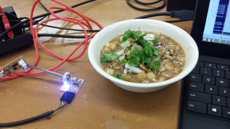
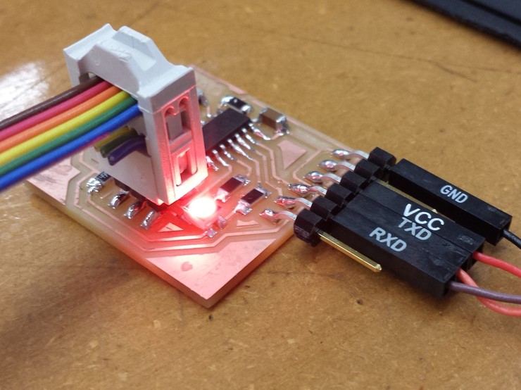
The board we created a few weeks ago can be powered either through the FabISP, or using an FTDI cable. The FTDI chip converts USB to a serial communication interface. We only use 4 of its pins, as shown by this janky cable with individual pin connectors:
If you have SJ2 still attached on your FabISP, I found that you can program and run your board without powering it separately. This isn’t supposed to work, though, so YMMV.
What’s a Makefile?
A Makefile is a set of instructions for the make command, which is
usually used in conjunction with compiling tools to make sure that
different pieces of code are built in the right order. Suppose you
write a large program with parts A, B, and C, and that B
depends on C. A proper makefile will compile C before B, and
A as well. Moreover, if you change just C, re-compiling will also
compile B, but not A. This can make updates to large programs much
faster.
More concretely, my makefile for this assignment looks like the following:
PROJECT=rainbow
SOURCES=$(PROJECT).c
MMCU=attiny44
F_CPU=20000000

CFLAGS=-mmcu=$(MMCU) -Wall -Os -DF_CPU=$(F_CPU)

$(PROJECT).hex: $(PROJECT).out
    avr-objcopy -O ihex $(PROJECT).out $(PROJECT).c.hex;\
    avr-size --mcu=$(MMCU) --format=avr $(PROJECT).out

$(PROJECT).out: $(SOURCES)
    avr-gcc $(CFLAGS) -I./ -o $(PROJECT).out $(SOURCES)

program-usbtiny: $(PROJECT).hex
    avrdude -p t44 -P usb -c usbtiny -U flash:w:$(PROJECT).c.hex

program-usbtiny-fuses: $(PROJECT).hex
    avrdude -p t44 -P usb -c usbtiny -U lfuse:w:0x5E:m

clean:
    rm $(PROJECT).c.hex $(PROJECT).out
You’ll see other lines in makefiles provided to you by the class, but they’re basically just instructions to program with other ISPs. This is the minimum you’ll need to get some code into a microcontroller with a FabISP.
To start, any of the $(...) sections are just variables. They
basically allow us to define some values and use them in different
places without typing them over and over. This allows the four lines
at the top to change the parameters of compiling the code. They denote
-
PROJECT: this variable is just calledrainbow. It’s used to generate the names of other files. -
SOURCES: a derived variable with a value ofrainbow.c. It’s file that contains the code I write. -
MMCU: this specifies the microcontroller type. -
F_CPU: this is the CPU clock rate. It’s used in compilation so that when we write code to delay for 100 ms, it actually comes out that way. We used a 20 MHz oscillator to design the circuit, so we need to set the right value here. -
CFLAGS: these are just arguments we’ll pass to the compiler.-Wallmeans print all warnings.-Osmeans don’t try to optimize the machine code. (Optimizing code can make it run faster, but may produce errors in esoteric cases.)
All the lines below this are called targets. We can build them by
typing make <target> at the commandline. This argument is optional;
if you just type make, it’ll try to make the first target. In this
case, make is equivalent to make rainbow.hex.
Each target consists of some dependent targets after the : (colon),
and then some commands. What make will do is recursively re-run any
dependent targets that have changed, then execute the commands. The
final target, clean, just removes any files that were generated
during the compilation process.
Just typing make will compile the code, then convert it to the
hexadecimal format for uploading:
> make
avr-gcc -mmcu=attiny44 -Wall -Os -DF_CPU=20000000 -I./ -o rainbow.out rainbow.c
avr-objcopy -O ihex rainbow.out rainbow.c.hex;\
        avr-size --mcu=attiny44 --format=avr rainbow.out
AVR Memory Usage
----------------
Device: attiny44

Program:     486 bytes (11.9% Full)
(.text + .data + .bootloader)

Data:         42 bytes (16.4% Full)
(.data + .bss + .noinit)
You can see that make is running the following commands:
avr-gcc, which compiles the code,avr-objcopy, which converts the code into a suitable format for programming,avr-size, which helpfully tells us how much space the program is taking up.
You can see that the Makefile makes it a lot easier than typing
those lines out, one by one. It’s also smarter and will not re-run
commands that will have no effect.
If this is your first time programming, you will want to run make
program-usbtiny-fuses, which sets some values in the fuses
(non-volatile configuration memory) of the microcontroller. Note that
this is a constant value so you don’t need to set it every time you
change the code.
The next step is to actually send the program to the microprocessor,
which is accomplished by the program-usbtiny target. This just runs
one command, using avrdude to send our binary file over to the
microprocessor using the usbtiny driver. If all works as intended, you
should see the following:
> make program-usbtiny
avrdude -p t44 -P usb -c usbtiny -U flash:w:rainbow.c.hex

avrdude: AVR device initialized and ready to accept instructions

Reading | ################################################## | 100% 0.01s

avrdude: Device signature = 0x1e9207
avrdude: NOTE: FLASH memory has been specified, an erase cycle will be performed
         To disable this feature, specify the -D option.
avrdude: erasing chip
avrdude: reading input file "rainbow.c.hex"
avrdude: input file rainbow.c.hex auto detected as Intel Hex
avrdude: writing flash (486 bytes):

Writing | ################################################## | 100% 0.51s


avrdude: 486 bytes of flash written
avrdude: verifying flash memory against rainbow.c.hex:
avrdude: load data flash data from input file rainbow.c.hex:
avrdude: input file rainbow.c.hex auto detected as Intel Hex
avrdude: input file rainbow.c.hex contains 486 bytes
avrdude: reading on-chip flash data:

Reading | ################################################## | 100% 0.27s


avrdude: verifying ...
avrdude: 486 bytes of flash verified

avrdude: safemode: Fuses OK

avrdude done.  Thank you.
Note that we typed two commands here: first make, then make
program-usbtiny. But because the program-usbtiny target depends on
rainbow.hex, you actually don’t need to type both commands; just
typing make program-usbtiny will both compile your code (if it has
changed) and upload it. Once you’re all set up, programming is as easy
as 1-2 (not even 3):
- Save your code in your text editor
make
program-usbtiny
Note that the flash memory on the ATtiny44 has an endurance of 10,000 program/erase cycles (it’s like a little hard disk, and not the same memory used to run code). So don’t get too trigger happy here :)
Side Note for Windows 8
When using avr-gcc on Windows 8 you may see an error like the
following:
0 [main] sh 2312 sync_with_child: child 4744(0x14C) died before initialization with status code 0xC0000142
73796 [main] sh 2312 sync_with_child: *** child state waiting for longjmp
/usr/bin/sh: fork: Resource temporarily unavailable
To fix that, follow the instructions in this post.
A Dazzling Rainbow
Once all this is working, it’s quite a treat.
By “Rainbow Soup” earlier I actually meant a rainbow plus a soup - some homemade pozole that I brought to the lab to feed fellow hackers on a Friday night.