Here is a link to a page on Instructables where I have posted details on my project.
As of the evening of 12/21, 1717 views and 53 favorites :)
And here are videos of my final project working, followed by an explanation of the steps!
Part 1:
Part 2a:
Part 2b:
_____________________________________________________________________
Back to the beginning...
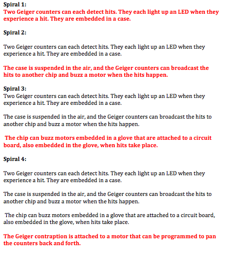
12/3: Neil mentioned how important it is to work using the "spiral" method
and I couldn't agree more: finish a simplified version of the project and then loop back
and add more features,rather than scramble to get the thing working in its full complexity.
I will be very diligent about only proceeding to the next cycle if I'm satisfied I've met the
demands of the previous one (for example, "build a case" is part of cycle 1, and even though
it feels less critical, it is nonetheless essential for my final product and so I won't move on
until I've completed it). I started off by defining
my "spirals" as follows (we'll see which one I get to! I hope I make it past #1 at least!)
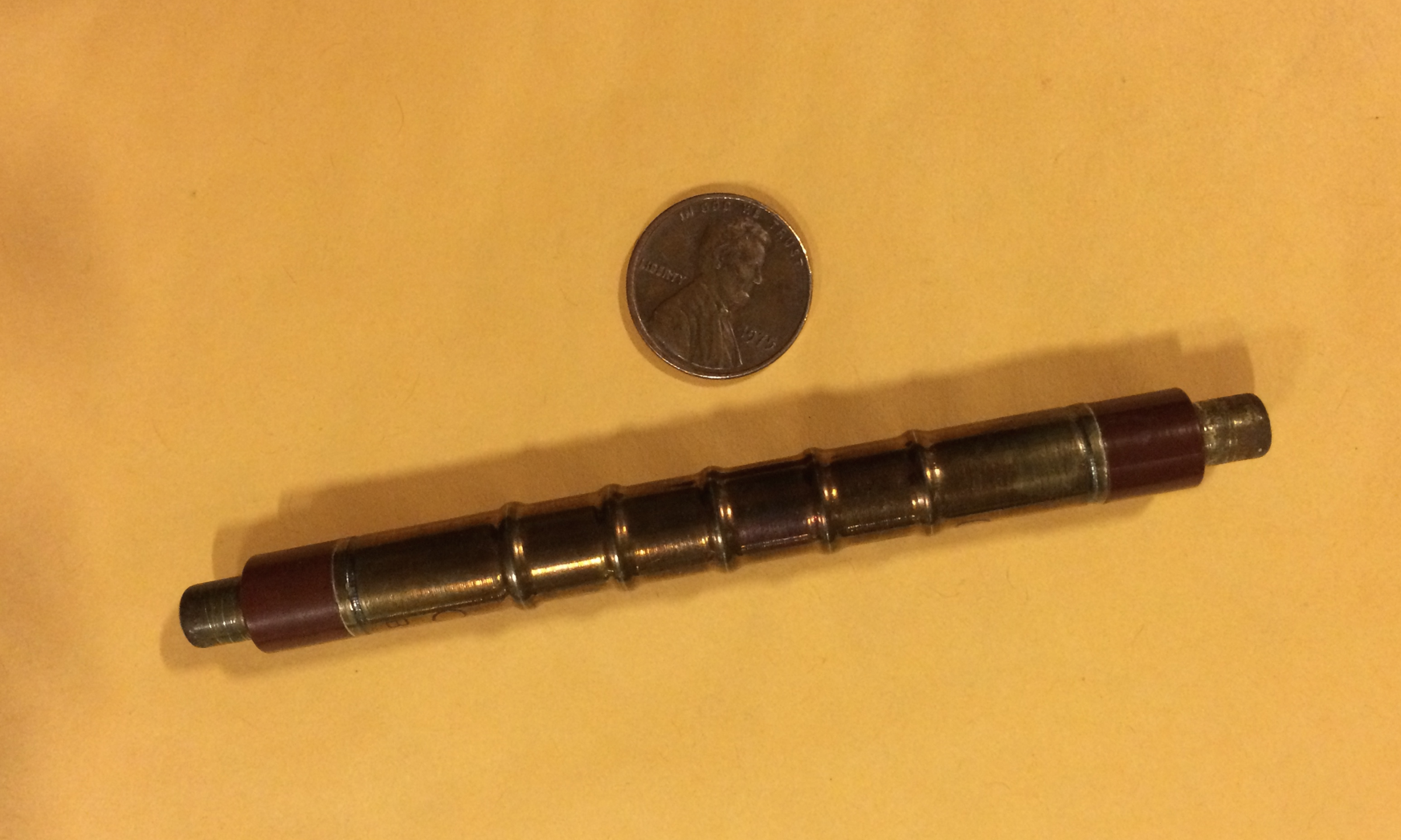
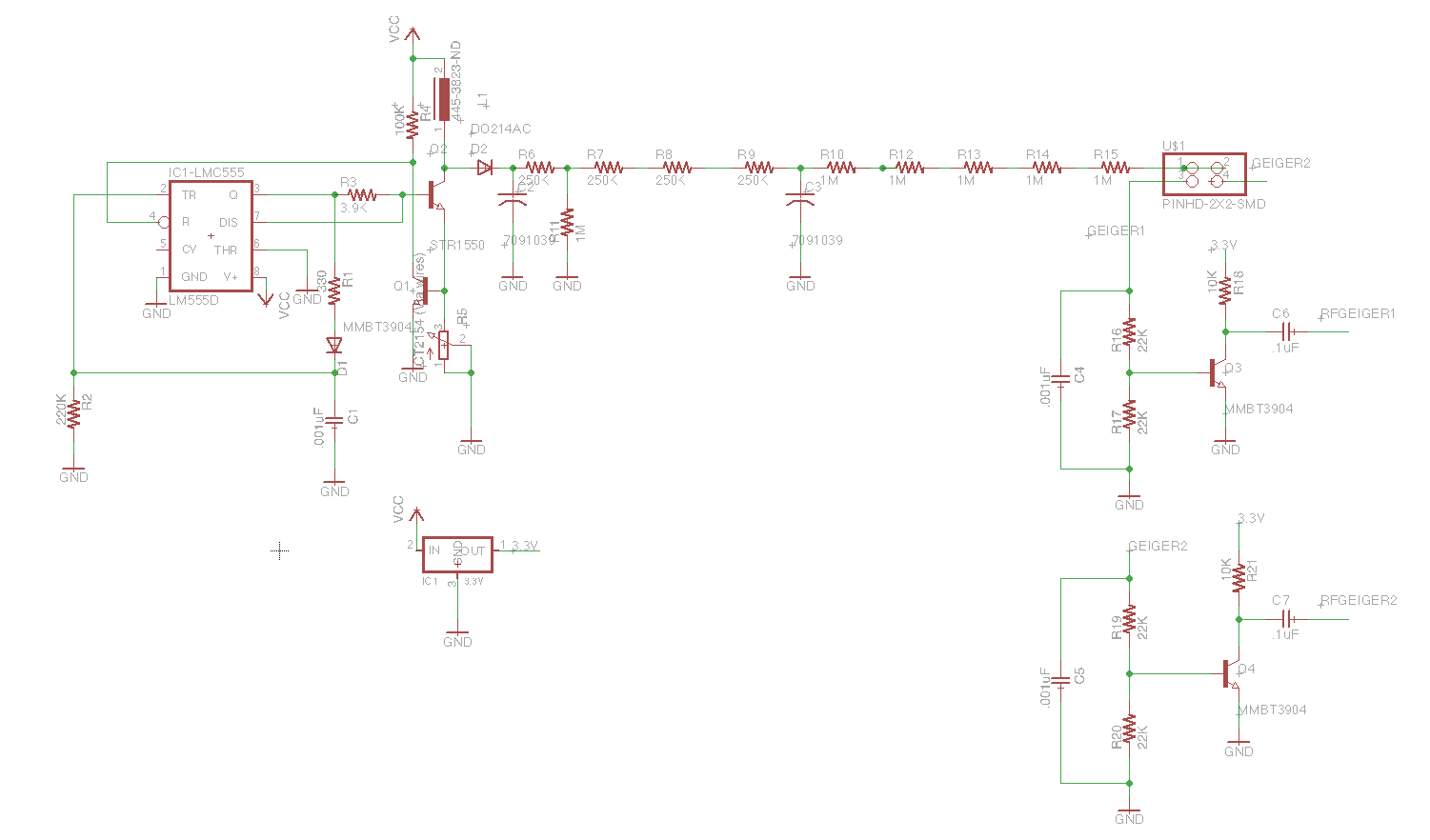
A few weeks back, I bought some old Russian SBM20 Geiger Tubes off of Amazon for about $20 each. You can get them for a little cheaper than that off of Ebay. They are from the Soviet Cold War era when Russia built many such tubes. You can find specifications for this tube here, but the most important thing to note is the operating voltage of 400 volts.
Honing in on my first cycle goal, I will concentrate on building a high voltage supply to power the tubes and a mechanism to detect small fluctuations in voltage that can be read into an RFDuino as a digital pulse.
12/4: I'm already a little disappointed with my progress. I got discouraged last
night trying to interpret geiger counter circuits, and the 'group machine' project sucked
time from everyone as well today. That said, this morning I did cheer up and analyze a chunk of
the circuit, specifically the chunk that makes a high power supply. Here's my explanation
for how the chunk of circuit below works to supply high voltage to the tube:
I'm not completely new to the 555 Timer (used it a lot in Physics 123) but it's been a while.
It's used as a timer, for pulse generation, and as oscillators (we previously wired it as flip
flops, but that's far from it's use here.)
So, let's analyze the circuit below, as best as I can (still don't understand everything).
The 555 timer is wired here in an astable mode to generate pulses.
For some reason R3 and and C2 determine how long the '555 is on and R1/C2 determine how long it's off.
Q is the output of the '555, which fuels the gate of the transistor....
NOTE: Images below are taken from internet...not yet my schematic!
http://kripton2035.free.fr/Resources/GK%20Build%20Instructions%20v2.pdf
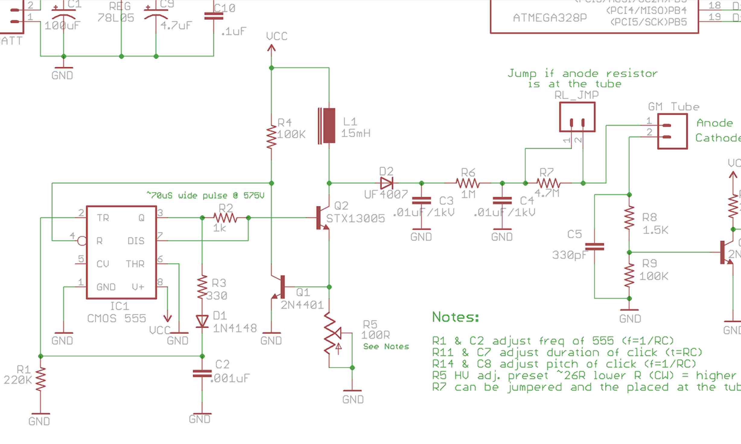
The next chunk of circuit in the HV supply is called a boost converter. and it creates the high voltage. It PWM's the voltage into an inductor When the transistor is on, current flows through the inductor, charging it. The amount of current sourced depends on R5. When Q2 switches off (e.g. when the '555 pulse is down) the inductor wants to preserve its previous current state, so to do so a big voltage spike will be induced. This voltage will be stored in C3 and C4. R7 is the geiger counter's anode resistor, and the geiger will be exposed to high voltage supply (and low current).
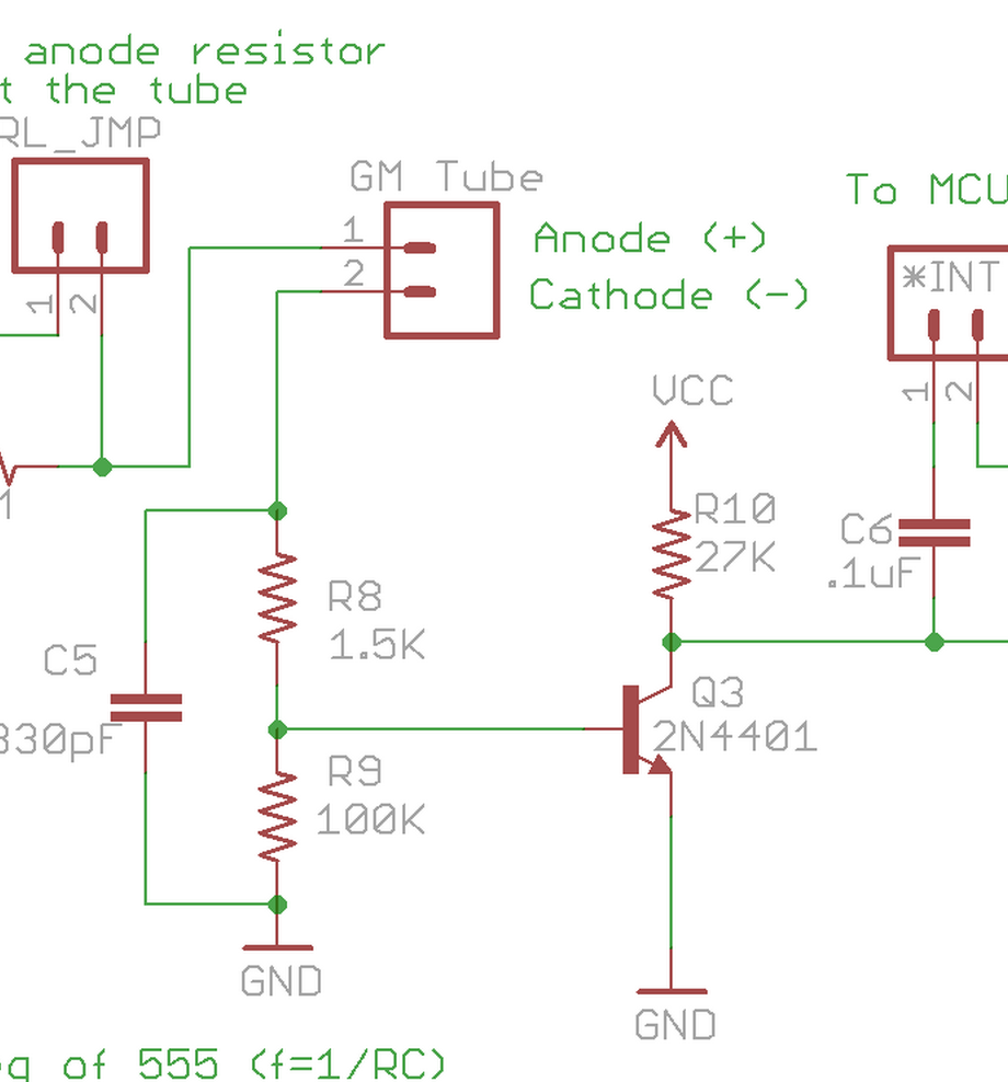
Next, the output of the GM tube is amplified by Q3 (the transistor), which will turn on and let current flow to the microcontroller (in my case an RFduino). The voltage output of the Geiger tube is reduced by the voltage divider and a bypass capacitor. I'm still not sure of the purpose of the bypass capacitor, but it has something to do with decoupling fluctuations on the left hand side of the circuit (which is AC) since we're about to feed this current into a transistor and then into a microcontroller and microcontroller circuits are designed as DC circuits. Some things that still trouble me: 1. I thought the cathode should be connected to ground? 2. We want the microcontroller to see fluctuations in the GM tube voltage is that we're meant to see fluctuations in the geiger counter voltage on the order of volts and should be measured across another resistor (where is this resistor in the circuit??) I'll ask these questions to JF tomorrow, but in the mean time, semi ready to roll! (I'm trying to get in the habit at the Media Lab of jumping into things even before being 100% certain of the plan, so now seems like a good time :)
PHEW! After much staring at parts, I finally settled on the following order. I'm taking a (possibly pretty significant) risk in relying on our shop's resistors rather than using my own (and subbing in the potentiometer above for static resistors, since potentiometers were expensive. We'll see if I regret that later or not :) I have only medium confidence that these parts will do the trick, but we shall see!
It's super late. Tomorrow, my goals are to: meet with JF to clarify remaining ambiguities about my application, order any other parts that he recommends, and then lay out my components for my high voltage supply and Geiger tube circuit in Eagle (it's probably going to be a real headache tracking down the Eagle part files for my somewhat more obscure part selections, but we'll see!). Stretch goal for tomorrow: I also want to start thinking about the next chunk of circuit- namely, how to interface my geiger tube pulses with my RFDuino.
12/5, Morning Ok. Met with JF. He was very helpful. A few general notes about the circuit that I now understand better:
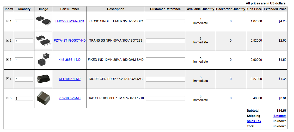
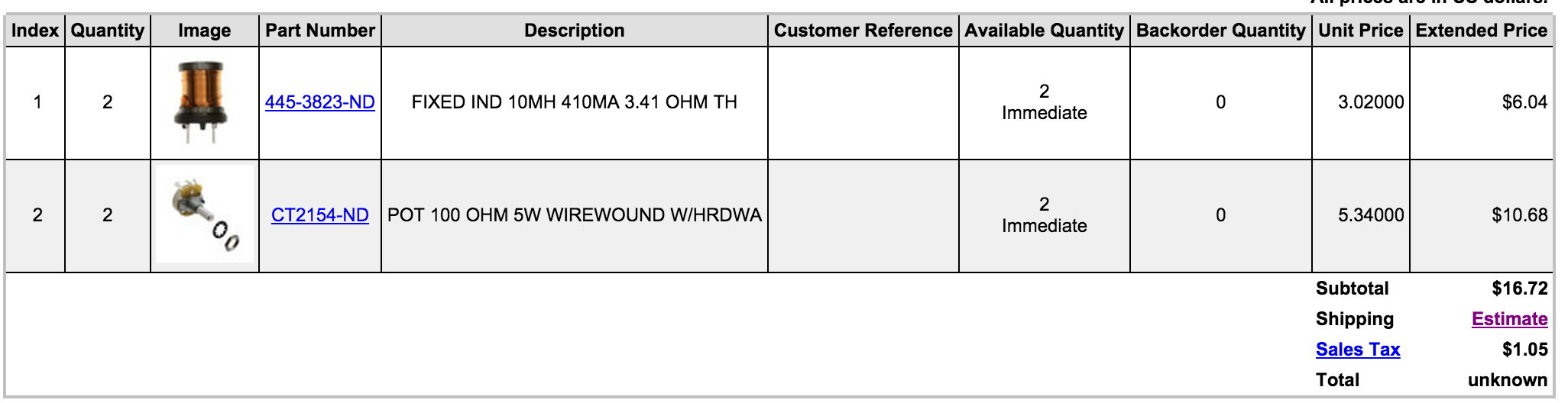
Following my goals outlined yesterday, I'll now order any other parts JF recommends (e.g. an inductor that can handle higher current, and a 100 ohm potentiometer even if it's not surface mount.) Alright, Order placed! Here are the parts I chose:
Next on my list from yesterday is to begin laying out my components in Eagle. Or should I work with the simulator first? Maybe I'll start in Eagle and then move to the simulator to tweak component values. Sounds like a plan.
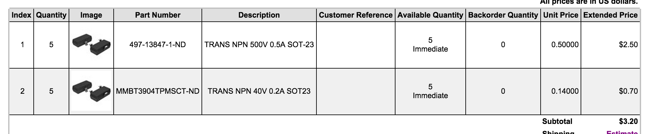
Well, more than ever Eagle has proven to be a real time sucker. I also realized that we don't have transistors in the inventory (only MOSFETs) and also that the HV transistor I previously selected might not operate under high current. So I put in yet a third order to Digikey for better parts:
I also met with Mark in my group to talk more about the '555. Still don't fully understand it, but I know understand that R1, R3, and C2 just impact the rate of the pulses emitted, and so for my application I don't really care much about that rate. Also, R6/C4 form a filter for the high voltage.
In any case, now that I've ordered everything I can imagine, I really need to move on with my Eagle schematic. New Eagle tip: "Smash" decouples the part label from the part so that you can move it around freely.
A few hours later: still at it, but progressing. I realized I'd need a way of attaching wires to my counter, so David gave me two fuse holders which are a start. I'll need to think more about mounting the counters on their own boards down the road. 6:45- time to meet with my "making machines" group :/ I have currently achieved my HV supply schematic, but need to work on the geiger tube->microcontroller chunk (I had hoped to get to the transistor switch today...maybe later)
Update: finished the tube->microcontroller. CONCERN: Will it be an issue that I'm feeding my high voltage supply to two geiger counters? For example, in doing so I'm increasing the load on the circuit and also reducing the current that will flow through each tube (then again the tube runs on extremely low current? Data sheet doesn't indicate how much...)
YAY I successfully accomplished my
goals for today. Tomorrow's goals: Purchase clear acrylic. Wire RFDuino to circuit schematic. Layout circuit board. Think
about power supply. Respond to JF feedback. SolidWorks model for acrylic, mill acryllic.
Stretch goal for tomorrow: mill circuit board.
I want to make sure I keep moving on the physical design as well,
so I'm going to be sure to spend some time on the acrylic piece..hope I can track down the material....
Goodnight!
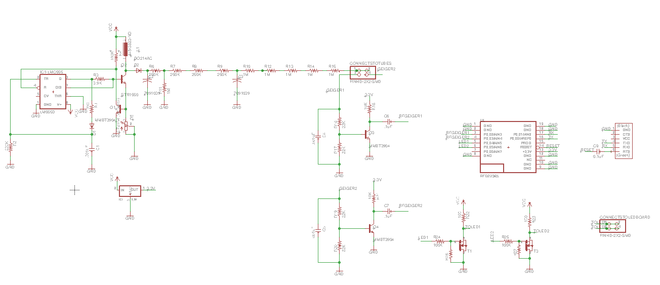
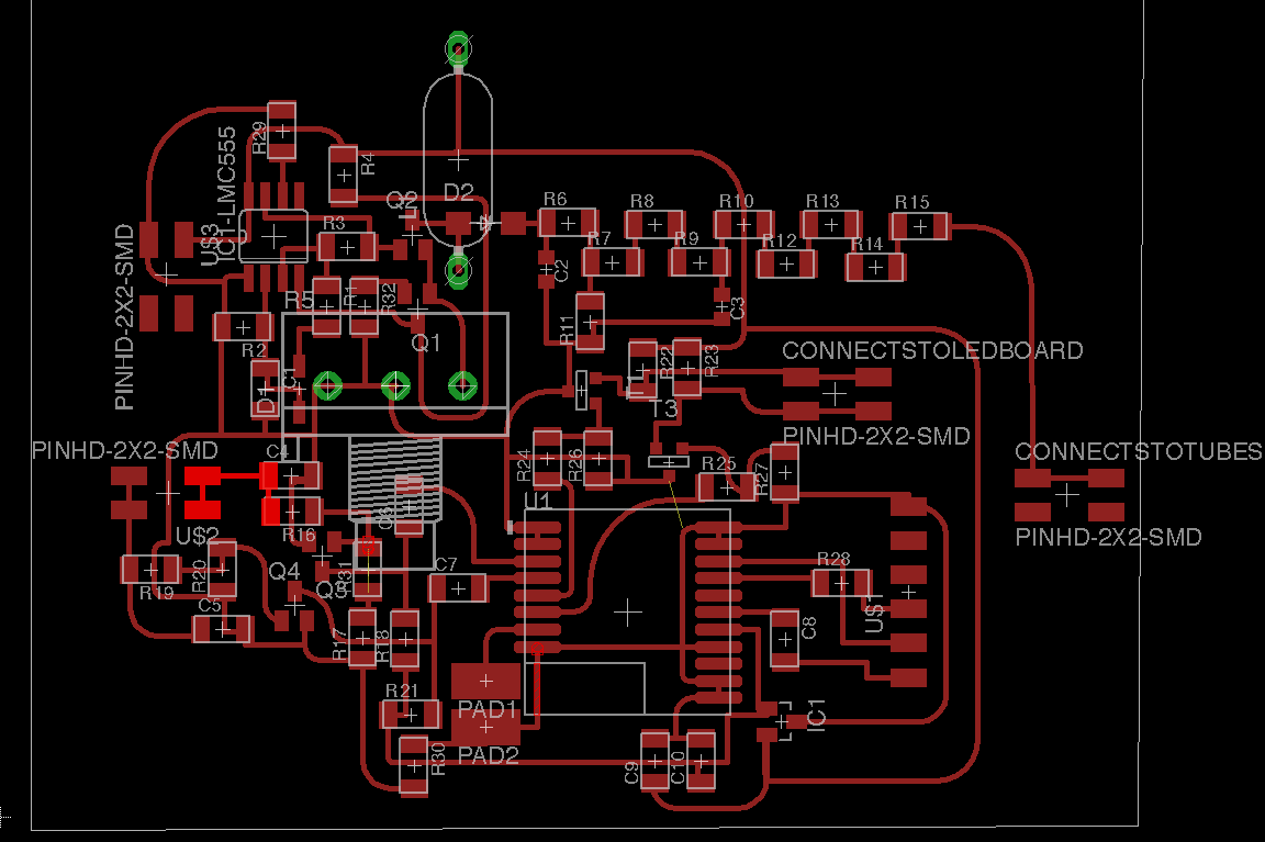
Came in around 12:30 today. I tried to find acrylic blocks at Blick and at Artist and Craftsman but neither had any :/ I'm thinking of just casting a brick. In the last hour, I added my RFduino and LED circuitry to the schematic, and if I'm not mistaken I think this makes me more or less done with the schematic! Still a bit lazy about calculating resistor values for driving my LEDs with MOSFETs...I'll figure that piece out later. I found some nice big LEDs in my lab and played around with them a bit with different resistor values since I don't know the LED specs. 10K was too large, 100 ohms was ok. Here's my finished schematic and LED below.
I'd feel much better if my casing work were underway, so I'll begin now. Since I couldn't find a plastic brick,
I ended up making an attempt to cast one in a cardboard box. Not sure it'll turn out, but from there I'll mill it.
Cardboard stuck, as expected, since it's a porous material. But that's ok, I'll just cut it off with a bandsaw.
Also managed to get my basic Solid Works model in place. Tomorrow: smooth out brick, mill brick (I'll need to mill
a few different sides to get my desired result), route circuit board.
I'm pretty bummed because I learned tonight that I could have gotten free 2-day shipping on my components thru the
Media Lab. Instead, I paid a ton of money and they may not arrive until Wednesday :( Well, onward!
Dec 7th..time is flying. Today my goals are to route and mill my circuit board, as well as to mill my acrylic based
on the model I designed last night. It's 1pm: I already have been at it for roughly 30 minutes...let's see how well Eagle cooperates...
Challenge: can I get this board laid out by 3pm? ;)
3pm LOL. Definitely not done. Oh Eagle.
3:37pm 8 more connections. Sigh.
3:41pm 7...
3:43pm 6...
3:51pm 5... [amping up my 0-ohm resistors...]
4:00pm 3... [not why my change fixed 2..]
4:07 1... [The hardest one though!]
4:41 BOOM. Done, and design checked, and wires curved. That took a whopping
4 hours to route. Eagle is serious business. There must be a better way.
After finally routing my board, I went downstairs and continued to try to cut the cardboard off of my plastic
block with the bandsaw by hot-gluing a bigger piece of wood to it. One more side to go. This evening I exported
my images (have some doubts about how to export the PNG for milling holes, so my current plan is to drill the holes
by hand.
I didn't finish my goals for today, but it's alright. Tomorrow my goals are to definitely mill my plastic casing
and to mill my board. I also want to submit for reimbursements.
If I have time, I will add some finishing touches to my holder. Sadly, my components still
haven't arrived (Some scheduled for Monday and others for Wednesday :( Silly me for not knowing about free 2-day
shipping). If I successfully finish milling my case
Before bed, I also investigated 2-way communication via RFduino. This has been implemented by RFduino using
GZLL, a wireless network protocol that allows a host to connect to up to 8 devices. In my case, I was thinking
that my host would be the glove, always listening for communication from the geiger tubes. So far, just one way communication.
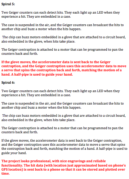
If I make it even further than that, I'll need two way communication since glove motion will trigger the motor on the geiger tubes.
Here's a youtube video I watched: https://www.youtube.com/watch?v=QcQ6KxWVG20#t=39
It's 1:18pm and I had a terrible morning...everything went wrong milling my plastic block and I need to entirely start again. I'm reducing my hopes for today to just getting my block milled. Ugh. This journal is meant to keep me forward moving and this morning I accomplished nothing and just moved backwards. Painful. No time for this!
It's 5:21 and it's only gotten worse. Mistake after mistake. I've thrown in the towel and I'm doing a two part holder, and cutting it all as a 3D part (the tool bed was misaligned which caused my last attempt to cut crookedly). I'm frustrated, I feel like I've wasted a lot of time, and I just really hope that this attempt goes smoothly and that I can move forward.
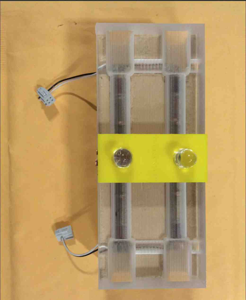
After a very frustrating day of milling something pretty simple, I finally got my basic case finished.
We also met for 3 hours for our group project and got a laser drawing machine up and running..super fun!
I went back upstairs after a long day to find fuse clips on my desk (will use these to attach wires to the geiger
counters...thanks labmates :) ) Then I went home to find 1 out of 3 packages from Digikey (sadly, the least
important one.
Tomorrow, my goal is to mill my circuit board and since I can't yet work on my geiger circuit, I will also
design and mill my glove circuit (should be significantly more straightforward than the previous circuit).
I was just daydreaming about some conductive fabric I saw at the lab...I wonder if I could embed strips of
this in my glove rather than have wires...Was also remembering that my glove requires an accelerometer.
12/9: Got in at 10:30. It's 10:50am now. I got larger copper plates from Tom and am now milling my circuit board. I'm worried about the fact that my two important packages haven't come yet, but trying to look on the bright side that this will provide an impetus for me to move beyond spiral 1 (though maybe also breaking the spiral model :/) Hope this attempt goes smoothly...
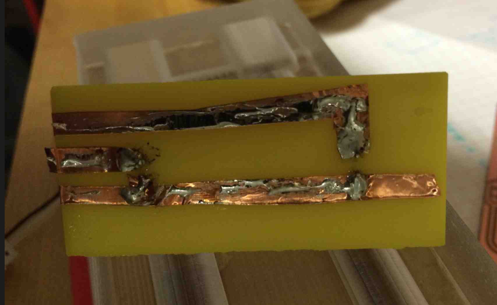
My wholes cut too big. I think it's because the path planning went around the hole as oppose to inside it. I should
have just made the circles dots. I wonder if this means I have to redo the board or whether some globs of solder. will
do the trick? I guess it depends on whether the larger holes cut other traces or not...
Results: holes are huge...but no other traces were cut so I might try to make do with it. We shall see. I
have a sneaking suspicion that at some point this week I'll have to make a change or two to my board anyway.
So if I do, I'll get those holes smaller.
Back from class. Goals for the remainder of the afternoon/evening are: attach wires to geiger tubes... Hmm. I'm really at a standstill because my package hasn't arrived. It's hard to know how to proceed. I've decided I should not move beyond cycle one...there's still so much to do for it, as tempting as the glove is. So, maybe what I'll do is make an LED holder. I just realized that I failed to include a ground pin for my LEDs on my board. Ugh. I'm thinking I'll cut the traces and add a few globs of solder to make two of the pins ground. No, that's not right either. I'm having one of my 'frozen' moments where I don't know how to proceed. Looking back at my cycles calms me down. So, hacky solution is: connect one side of LED to power, connect a resistor across where the 2x2 previously went, and then I should be good. (This isn't a great explanation but it's just for my own reference)
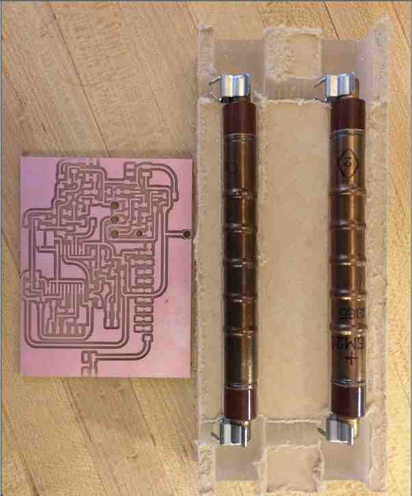
I finally laser cut my LED holder! I used copper tape underneath:
And here are some shots of the rest of my work between yesterday and today:
I did a pretty good job with today's goals! It's 10:15pm. I'm going to aim to do 2 more things tonight: Locate stepper motor, and SolidWorks model for stepper motor holder. It's silly but I had a change of heart- I'd be so sad if my final product doesn't move..so might choose to prioritize stepper motor over glove (and hopefully do both still!!) I also desperately need to start studying for my physics exam.
Tomorrow's pre-class goals: solder on the basic '555 circuitry so that I'm all ready when my CMOS surface mount '555 arrives, stepper motor board schematic, layout, Tomorrow post class goals: mill, stuff. Tomorrow at 7pm: stop project, 4 hours of physics studying. Note: I want my motor board to have a "start" button on it.
I realized that I only allocated one port pin on the RFduino for my motor. That is ok. I realized it just
means I'll need to move forward with the following solution: glove relays analog acceleration value to
RFduino on geiger tubes, this value is fed into a port pin of a separate microcontroller running the motor,
and this second microcontroller has code on it to map analog input of acceleration to the appropriate motor
controls. In other news, looks like my packages will be delivered today! (Yay, finally).
I'm having some trouble deciding what motor to use this morning.
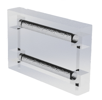
My geiger holder is pretty heavy (in retrospect maybe lasercutting thin acrylic into a box would have been a
better way forward). But thats alright! There are definitely motors that can handle high torque.
Time for class. My components arrived so I went home to get them. I laser cut one panel for my motor holder
but was unsatisfied with it. At this point I'm getting nervous and think I need to go back to my primary geiger
circuit before playing with motors anymore. But at least I've put some thought into it all now.
So, game plan is- after class, spend all evening with my circuit, moving from left to right. I need all the time
I can get to get that circuit up and running, so it needs to take priority.
Once I'm feeling a little better about the circuit, then I can come back to motor stuff.
I started out by stuffing the '555 portion of my circuit. I stacked resistors to get the appropriate values,
and I had to substitute a Schottky diode for a normal diode. Schottky diodes have a smaller forward voltage
drop which could potentially affect the rest of my circuit, but I suspect that all of these values are fairly
lenient and just effect the rate of my '555 pulses overall. We shall see.
7:15pm: experiment #1: Wired '555 with caps, resistors, and diode. Result: trigger and output are always high.
Mark helping me big time. Joe suggests Beeswax to insulate HV area once I'm satisfied with the circuit.
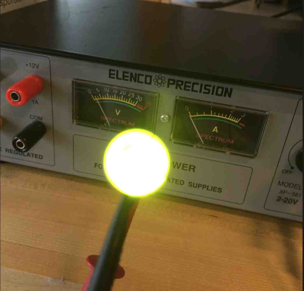
3:32pm: I'm satisfied with my HV output! I've wired up all the circuitry from HV->Tubes and Tubes->Signal.
So time to test my tubes...very scary because if the tubes perform questionably I might be screwed..Here goes nothing.
Not happy with regulator...I don't see 5v across Vcc/gnd pins..I am going to go down and replace it.
Realized it wasn't the regulator, it was that I was missing a ground connection. Actually, just missing a 0-ohm.
9:30pm- I'm pretty exhausted. Signal looked decent! Some worries though are: the signal looks like a sudden oscillation,
so I'm worried about detecting it as just a single hit. There also aren't as frequent hits as I'd hoped, so that's unfortunate
because it means hardly any cosmic muon hits at all. But on the bright side, I'm getting something, and can do an analog read
in to mess around with the signal.
Alright, guess it's time to program my chip with a simple LED program!
Port wasn't showing up...turns out there was something weird with my USB drives as they weren't working for any
device. Restarting my computer fixed whatever the problem was, and I was able to successfully upload and run
the sample temperature sensor program.
Some links I've been using:
http://mightyohm.com/files/geiger/Assembly%20Instructions.pdf
http://dl3etw.darc.de/Geiger%20counter%20homemade/Geiger%20Counter%20Home-Made%20Documentation%20REV0.pdf
Have been worse at notes...sorry. Working nonstop on this.
1 minute with no sample nearby: 28 hits, no simultaneous hits
1 minute with sample nearby: 64 hits, no simultaneous hits.
LED's working! I can't believe I made the mistake YET AGAIN of flipping source and drain on my MOSFETs. Soldering upside down and sideways it is.
The LEDs are a bit dim...don't quite know why. Maybe they're designed to be operated at higher voltages..I don't have the spec. Using only a 100 ohm
resistor for current limiting...
12/13: I'm almost entirely focused on studying for my other exam now, but during a 20 min study break I got a motor
to buzz via Bluetooth every time Tube #1 is hit...RFDuino's GZLL library made this host->device communication a piece of cake!
12/15: constant work/exam studying. Built case. Had to tweak press fit for case. Switched out unwieldy wire connecting inductor.
About to replace current limiting resistors for LEDs- was using 100 Ohms/5 volts which would cause 50mA which is probably
too high for LED.
I thought I fried my chip after flipping power and ground on my glove. Fortunately it was just the regulator. Replaced regulator and all was well.
After 3 hours of assembly/wiring, I can very happily say that my project works! (Monday, 5pm. That leaves 7 hours for studying for my exam tomorrow :/:/)
I'll post videos during a study break on a separate page, and I'll do complete documentation after tomorrow.
Pretty stoked! Now you can feel radiation particles in your vicinity!