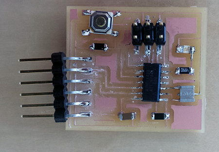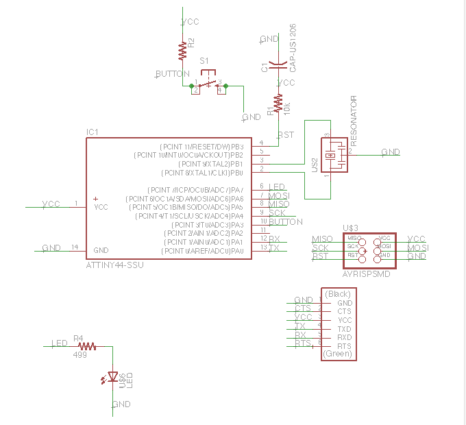
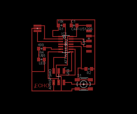
Step 1: Design the circuit board using Eagle.
To make a board, we used Eagle to map out a circuit. In eagle there is the diagram and the circuit.
The diagram is where you add the parts (be sure to download
the fabisp library to use for your part sources). The circuit is how
you arrange the parts to fit into place.
A few tips when using eagle:
* If it connects in the diagram side, it will connect in the circuit side.
When working in the circuit side of eagle, if you want two parts to connect —
for example all the VCCs — right click on a line/connection,
add a label. Right click that label and select Name. Then
name each line segment that is the same. This will make it
so pieces automatically connect (with thin yellow lines)
on the circuit side. If something doesn’t connect on
the circuit side, it’s like it’s not named or not named correctly.
* If you named it and it still doesn’t connect, it’s probably
because the line extending from parts on the diagrammatic side is not
correctly linked. Lines from the parts should start at the end of
the extension lines from the part. I included the big diagrams here
as reference. I found it was hard to find good references that were
good quality images - so hope they help!
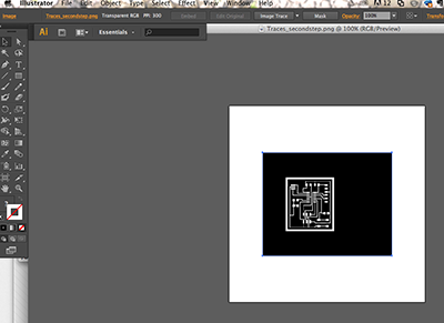
Step 2. Insure the circuits are in black and white.
Move to the echo board.
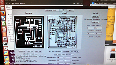
Step 3. Mill the circuit board.
Use modela to mill the circuit. The fab modules helped. Here’s what the path looked like.
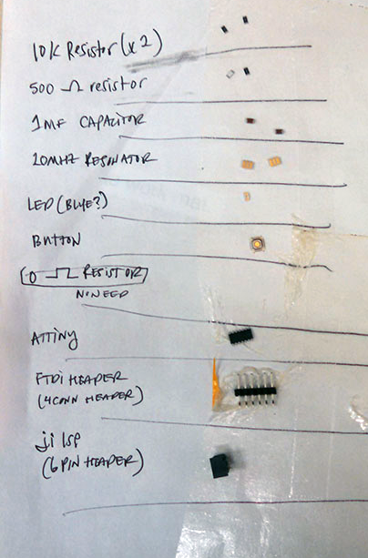
Step 4. Stuff the parts.
