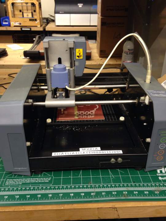
Step1: Milling a PCB (tracing)
I started this process following Jeff's online tutorial. I especially paid attention on cleanliness of the base, zeroing and tightening endmills to a collet, because those are the procedures which rely on user's skill and make difference in outcomes. The process was pretty straightforward. After first milling, some portion of circuit tracing weren't milled.(I forgot to take a picture...) So I adjusted the cutting depth from original setting of 0.1mm to 0.15mm and cut again. At the beginning of the Step 1, I should have checked whether it was halfway-through milling or not by using "View" function of Modela. The second time milling process went well, and I of course checked milling condition using "View" fuction.
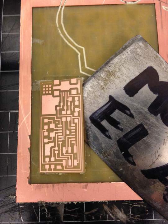
Step:2 Milling a PCB (outlining)
I replaced an endmill from 1/64 to 1/32 and did zeroing again.This Step went smoothly without any issue. One thing I cared about was checking the cutting depth. I used default setting first, and I confirmed the circuit board were cut through before I took it out from the base. I cleaned the board, and cleaned up the base.
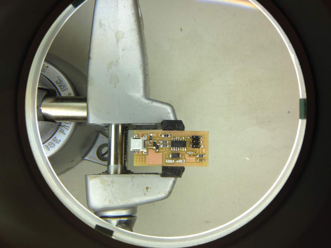
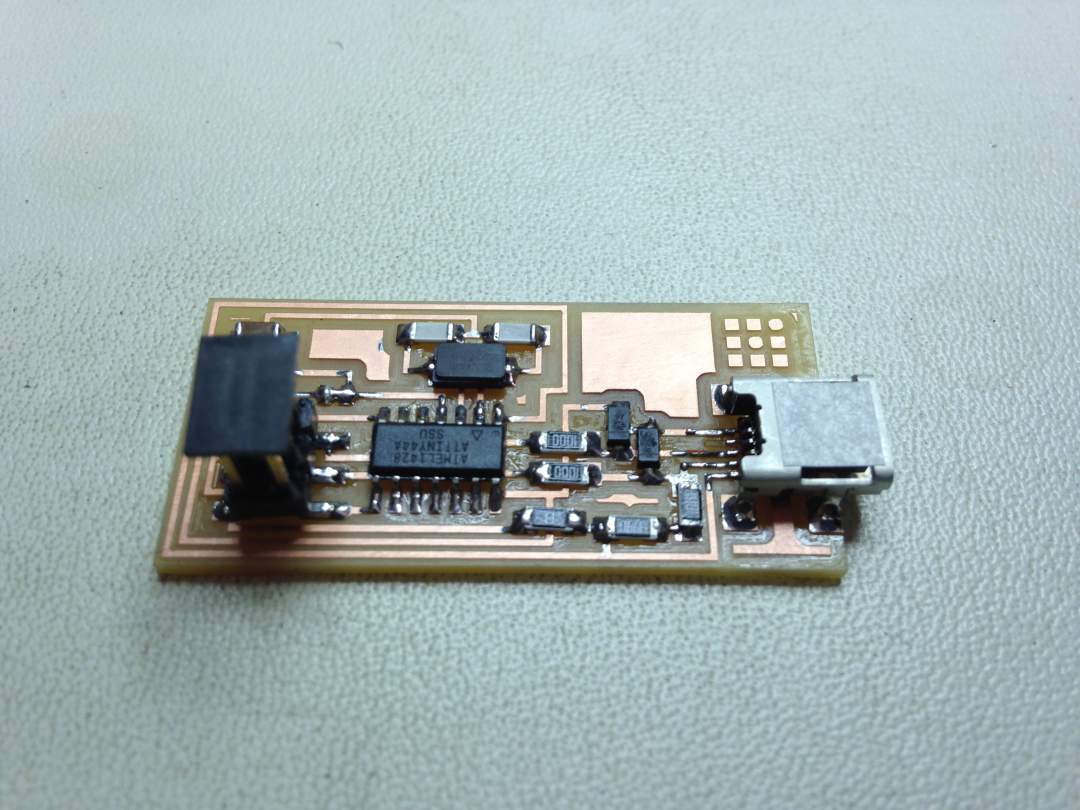
Step 3: Assembly/Soldering
I put flux on the board to prevent oxidation of the base to facilitate soldering process. As the room lights were not bright enough, I used a magnifier with light. I set temparature of soldering iron at 720 degrees celcius. I started to solder from smaller pieces such as resistors and capacitors to allow me to solder one by one easily. I put each components smoothly but I was not quite sure about the appropriate amount of solder for each components.
Step 4: Final Product? Not yet. IC was soldered backward
After I completed soldering, I found one big mistake. I soldered IC backward.
Step 5: Desoldering an IC
I didn't want to remake everything from a scratch, so I desoldered IC following this tutorial video. First, I stripped some thin copper wire, and soldered end of the wire to make it slightly harder. After adding some flux and some solder to the IC pins, I removed the excess solder using solder wick. I inserted the copper wire behind the IC pins, then applied the soldering iron to each pin while pulling wire to remove each pins from PCB. I did the same thing for both side of pins. I successfully desoldered and took off IC.

Step 6: Failed re-assembly
When I assembled new IC, I used solder wick to remove the excess solder. As the wick soldered to the PBA, I tried to take it off by heating it. But it turned out that I ripped off copper skin from PCB with the wick. Yes, I ended up to make new one from a scratch.
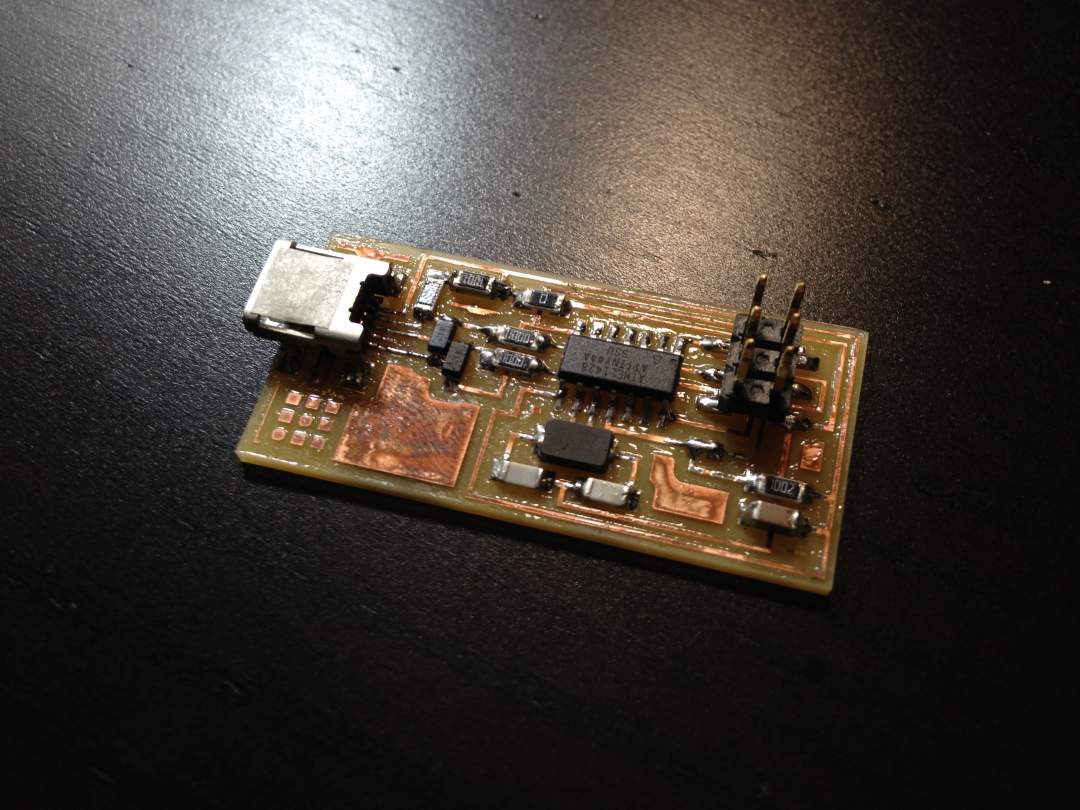
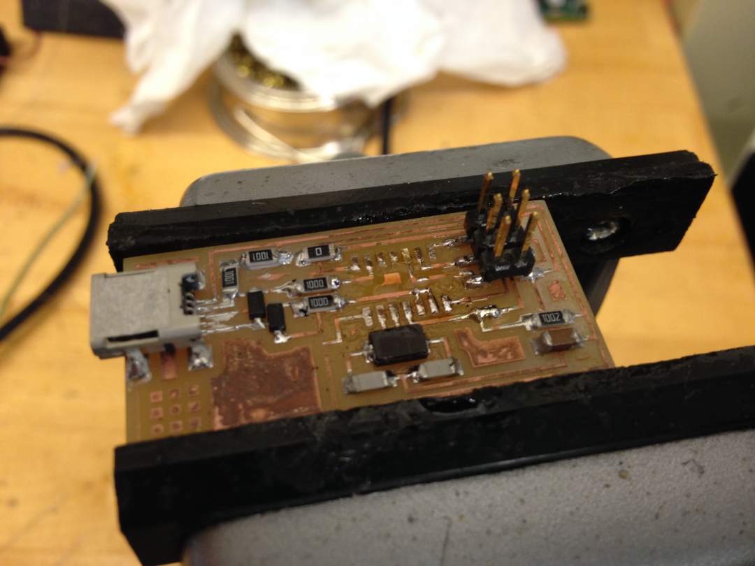
Step 7: Final product
Second attempt went quite smoothly. I cleaned up FabISP using flux remover at IDC lab immediately after I assmebled all components. And I checked continuity using multimeter. I hope mine won't have any issue on programming phase. Finally done!