Step 1: Determing high level function and specifications
I started this project with defining functionality, how this product would perform. Below is the general functionality and specifications.
Basic Functionality of the product
- Small plane and neat-looking device with red LEDs
- Send notification (vibration and sound) to a smartphone when accelerometer senses abnormal acceleration when the laptop is about to be stolen
Specification
Input device
- accelerometer (MEMSIC MXD6235M 2-axis accelerometer)
Output device
- 3 arrays of red LED light (For notification of the device is ON/OFF)
Network/Communication protocol
- Bluetooth module (HC-05 module)
Android App
- Activating Bluetooth
- Getting notification from the device and give popup window notification, sound and vibration to user
Exterior
- 3D-printed white color case
- Size: 25mm*50mm*100mm
- Have window for switch
- Have window for LEDs
- LEDs should be covered
- Marked "MAS863.14 How to Make (Almost) Anything," and "MIT Sloan logo."Power source
- Battery (9V)
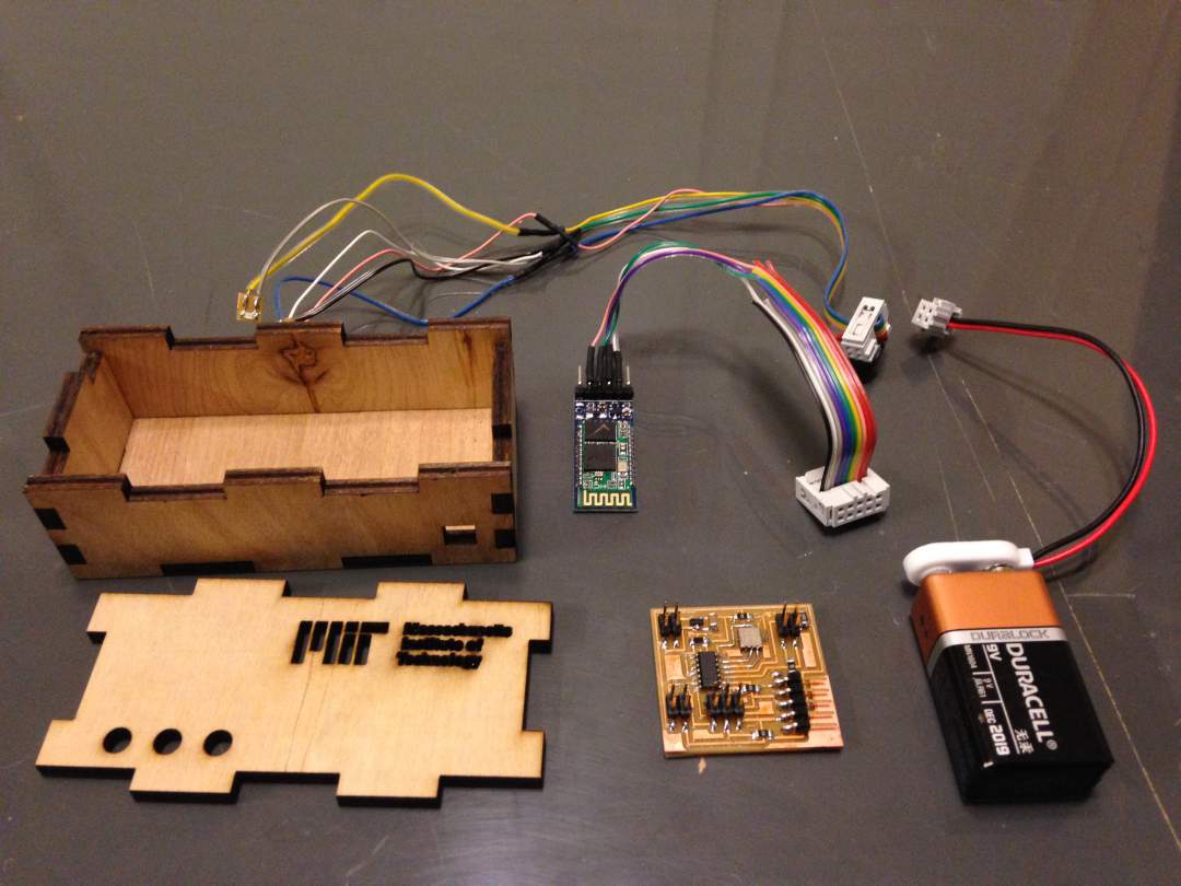
Here is a BOM for this product. All materials were basically available at IDC.
| Material | Vendor | Q'ty | Cost |
|---|---|---|---|
| 5mm plywood (2x4) | Homedepo | 10cmx20cm | $5.80 |
| 9V battery | IDC | 1 | $7 |
| HC-05 | IDC(JBtek) | 1 | $9 |
| MXD6235MP | IDC(MEMSIC) | 1 | $4.49 |
| Attiny44 | IDC | 1 | $1.52 |
| LED(red) | IDC | 3 | - |
| 2x3 header | IDC | 1 | - |
| 2x2 header | IDC | 3 | - |
| FTDI header | IDC | 1 | - |
| 100mA 3.3 V regulator | IDC | 1 | - |
| 0Ω registor | IDC | 4 | - |
| 10KΩ registor | IDC | 1 | - |
| 499Ω registor | IDC | 2 | - |
| 10μF capacitor | IDC | 1 | - |
| $27.66 |
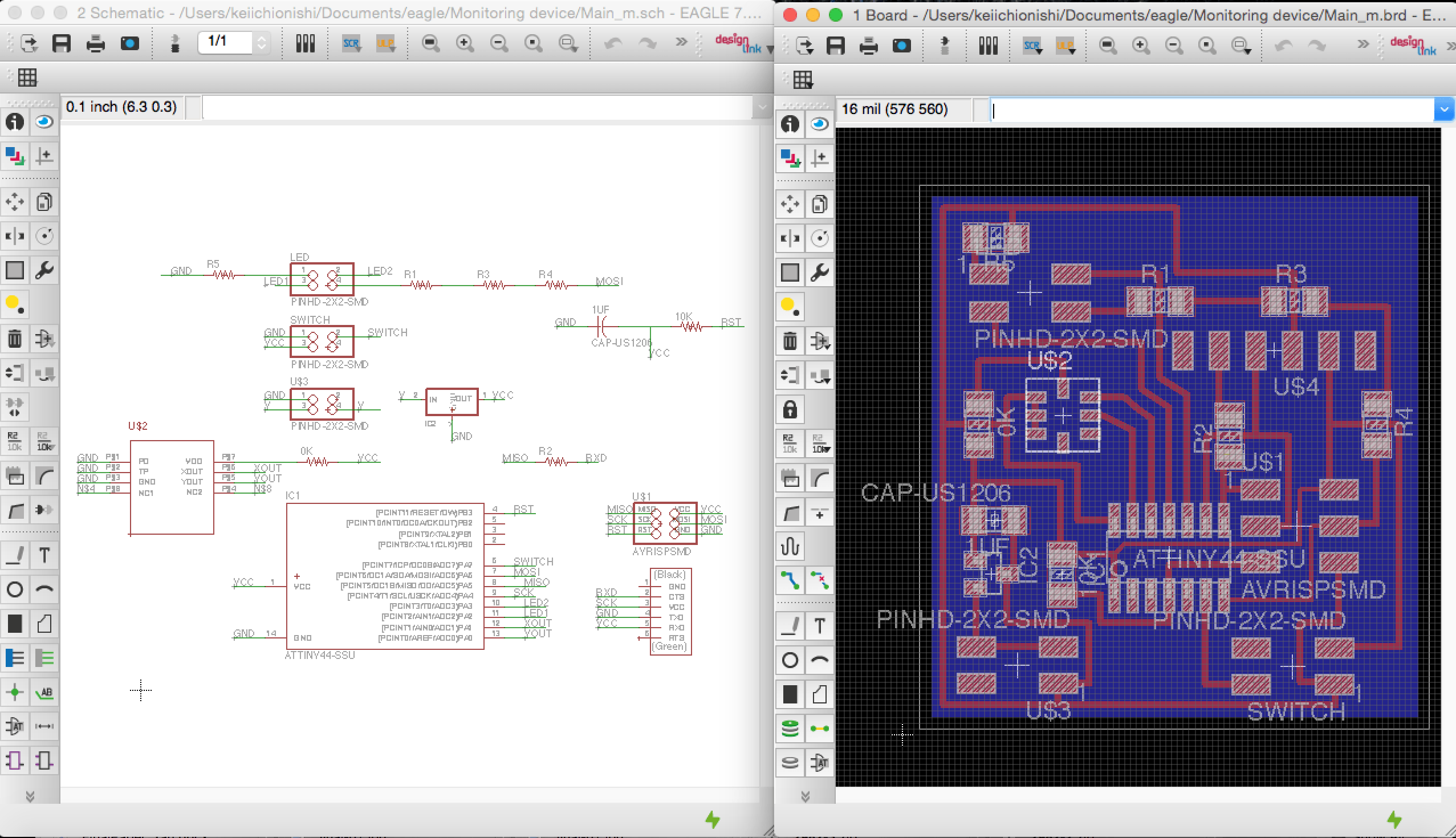
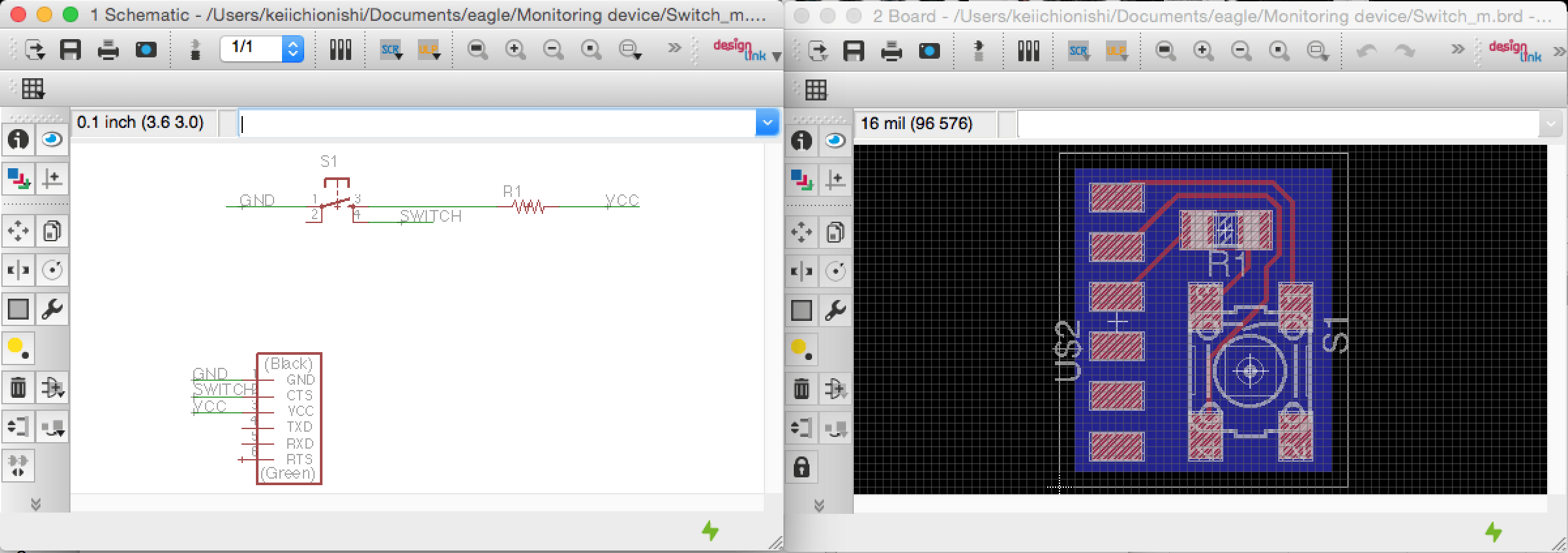
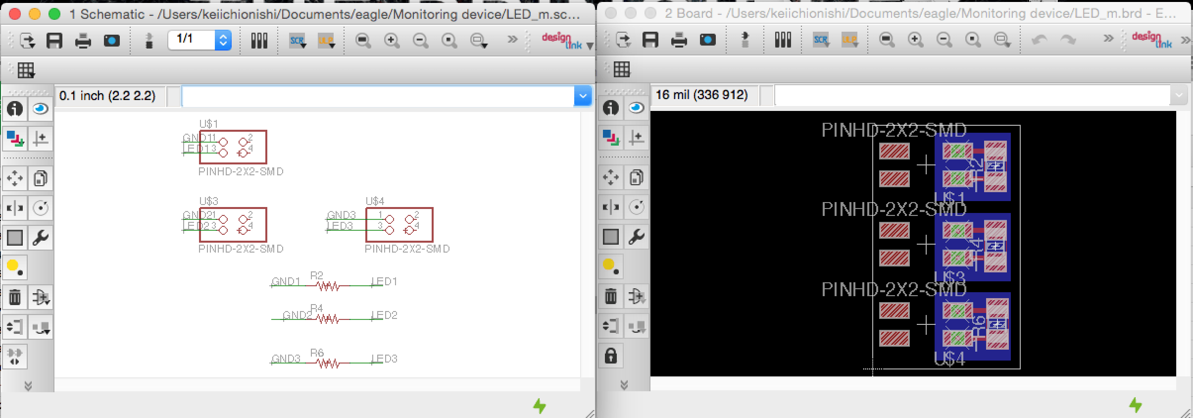
Step 2: Designing circuit boards
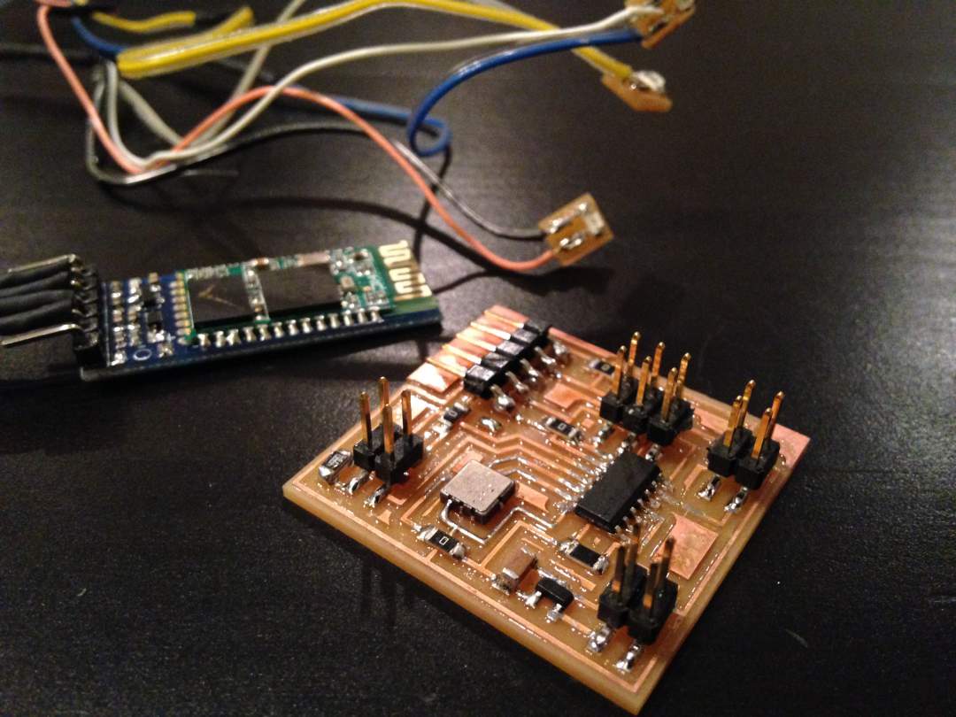
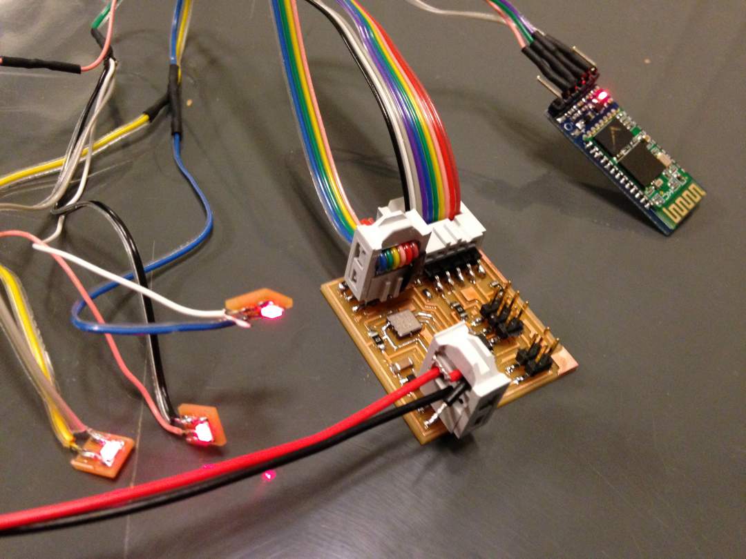
I designed total three boards - main circuit board with Attiny44 and 2 axis accelerometer, sub circuit board for mechanical switch, and sub three boards for LEDs. By utilizing knowledges you learn from series of electronics design and production, you should be able to design above circuit boards pretty comfortably. The most important part when you use accelerometer and bluetooth module is figuring out appropriate pin assignment reading datasheets of those and Attiny. Talking about bluetooth, you have to make sure you connect Rx and Tx pins of bluetooth module to TX and RX pins of Attiny. Also MXD6235M was not in the Eagle Library, I learned how to design and add new parts to the library from this tutorial.
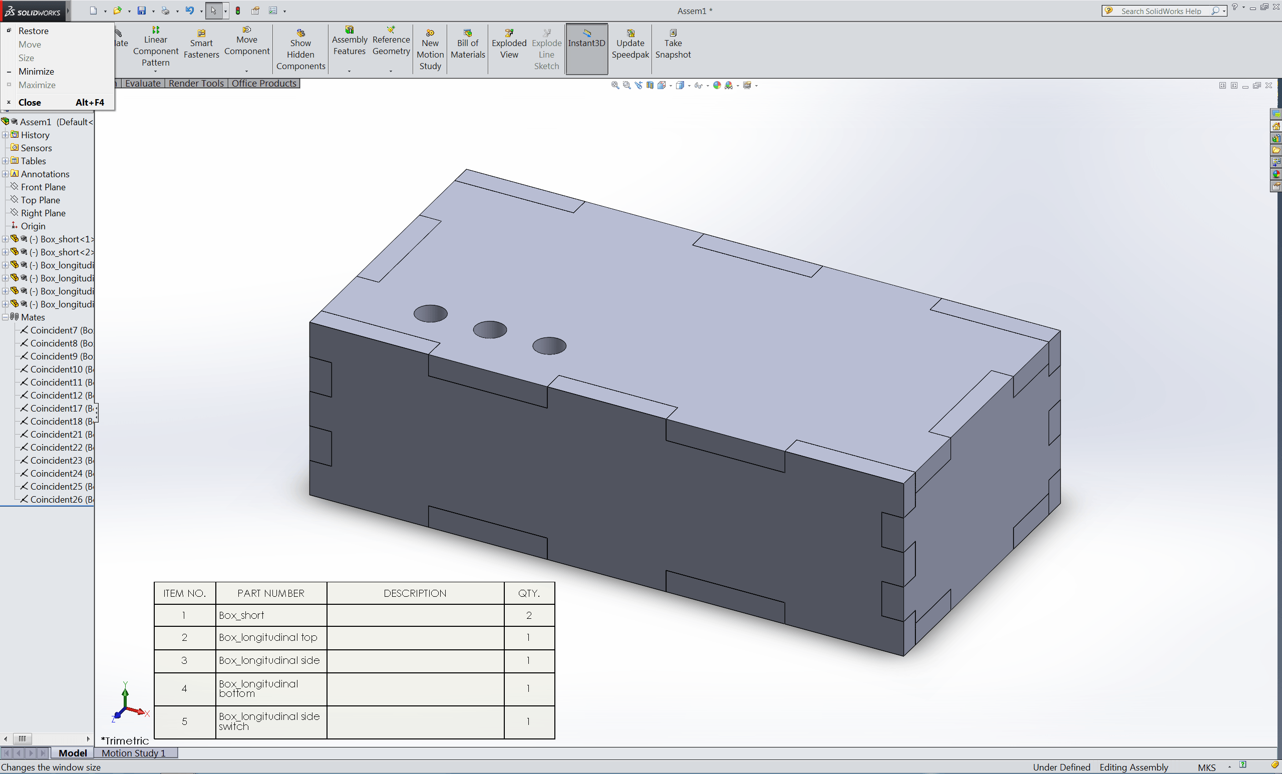
Step 3: Designing exterior
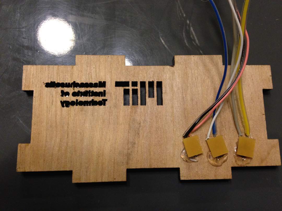
To build working prototype as soon as possible, I decided to build a simple box as exterior. I designed it using SolidWorks and saved a 2D drawing which contains all components as DXF file to allow CorelCAD to read the file. I also wanted to put MIT logo on the top of my product so I downloaded a png file and converted it into DXF file using Inkscape. This tutorial would help you to learn how to do that.
Step 4: Fabricating circuit boards
As experiencing several iteration of circuit board fabrications, this process went smooth as well. Neil sometimes mentioned that "design and make new PCBs rather than using those you made during previous assignment," which is so true. Through several iterations you could learn how to solder beautifully and quickly, and most importantly would spend less time on debugging circuit boards due to stupid mistakes. After I build PCBs, I checked connection using multimeter and they looked all good.
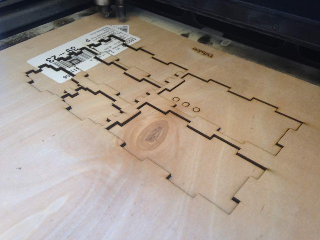
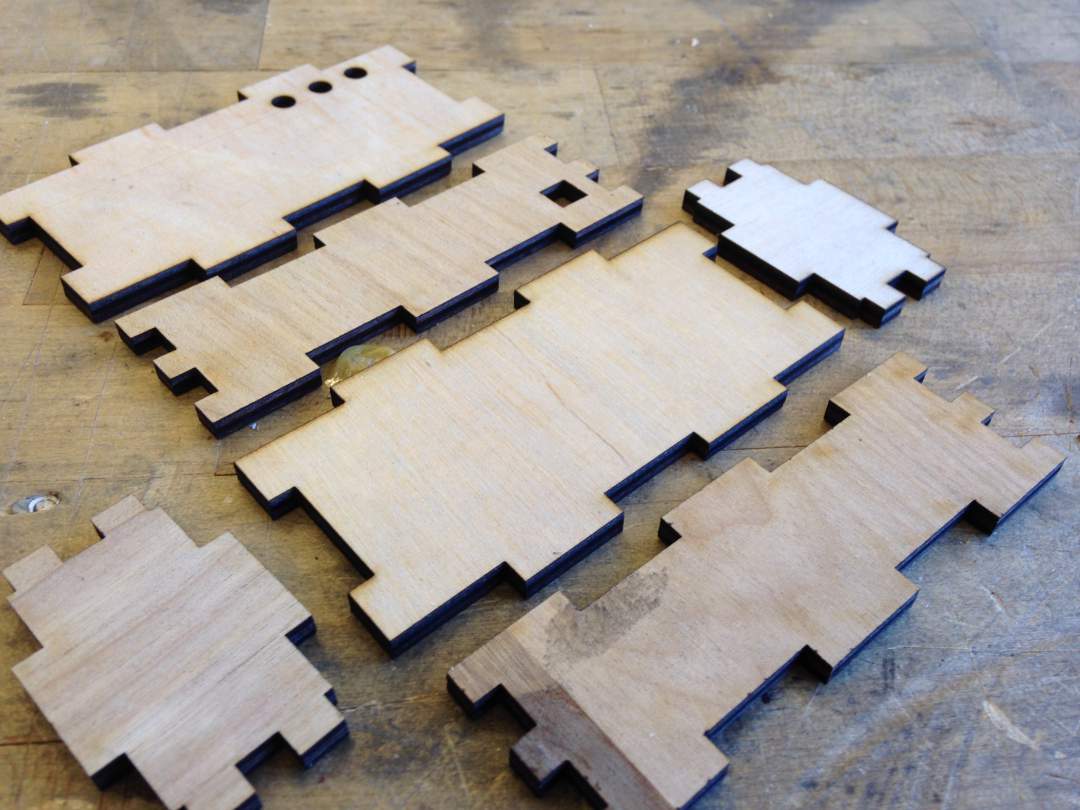
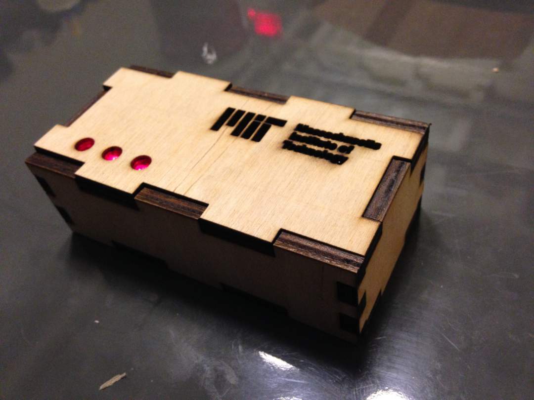
Step 5: Fabricating a case
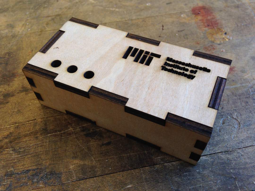
I cut plywood with laser cutting machine in IDC. After cleaning up a lense of laser cutter, I turned on air compressor and laser cutter. I opened 2D components drawing saved in DXF file type in milimeter (I designed the model in units of milimeter), imported MIT logo and arrange it on one of the component, and defined all line as hairline. When you do printer setting, open preference and make sure you load appropriate setting from "advance" tab. I chose 6mm plywood sheet for my 5mm plywood sheet, which works perfectly for that. I assembled all components and got a box.
Step 6: Programming Attiny44
This is one of the moments of highlight I struggled with. I used Arduino IDE to program the Attiny44 for the first place to use SoftwareSerial. I found Arduino libraries consumed so much memory storage that I couldn't use float or double for variables that were voltage values an accelerometer sends out. I ended up using int variables without casting values into float just using analogRead() function. Even if I used only two integer variables with SoftwareSerial, my Arduino sketch reached to 3800 bytes.
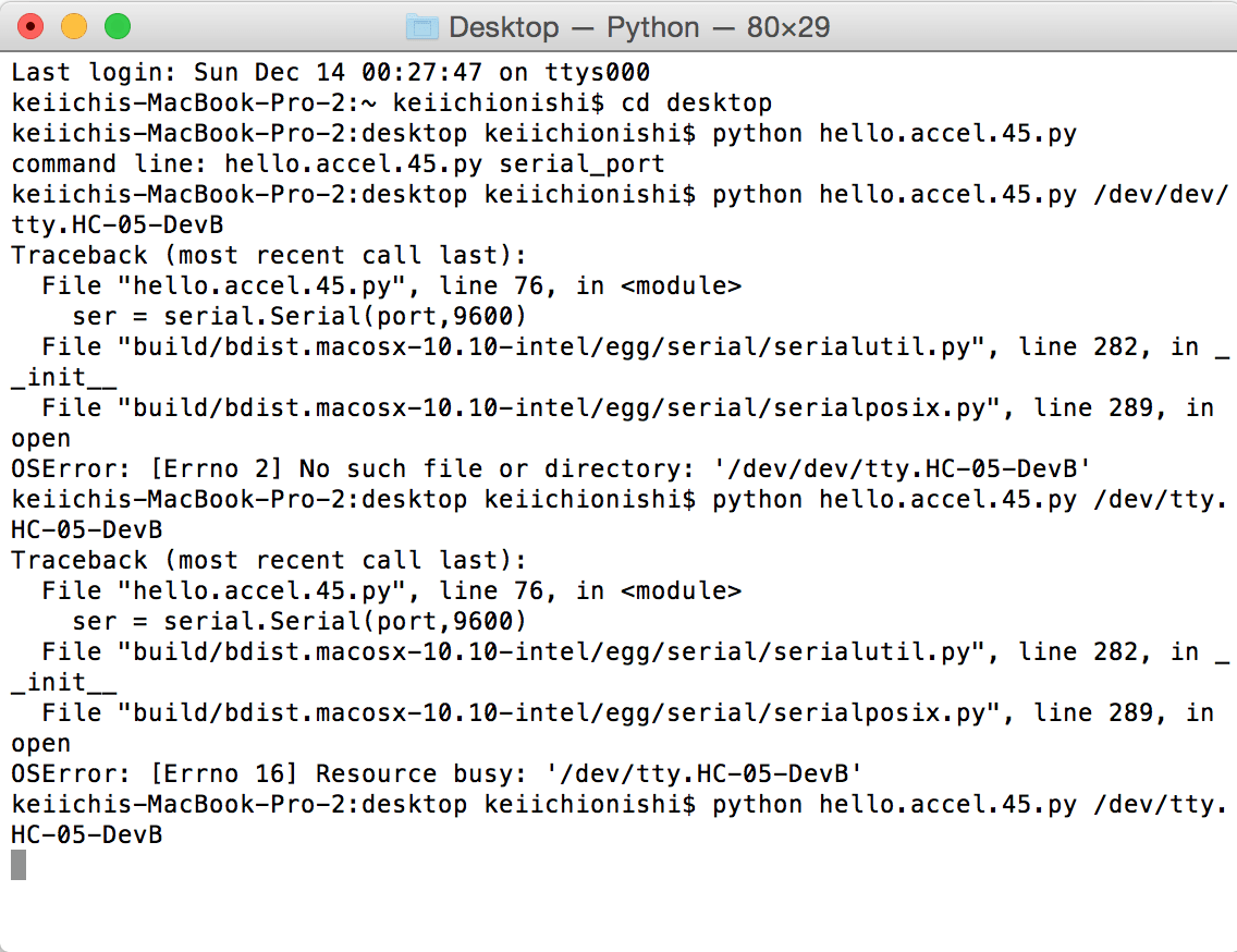
After I powered on the circuit board and connected to my Mac, I found I got only value of 0 or 1023 from the circuit board with bluetooth module, monitoring them at Terminal. This happened because of specification of the accelerometer's output signals. MXD6235M provides two digital outputs that are set to 50% duty cycle at zero g acceleration. The outputs are digital with duty cycles (ratio of pulse width to period) that are proportional to acceleration. This means we need to compute magnitude of accerelation from frequency of HIGH/LOW state switching per unit time. As I mentioned, I had have already realized that 4K internal memory of Attiny44 was not enough to add additional variables and functions. So my only option is programming the microcontroller using C with minimum required libraries and basic functions. I went back to lecture about Input devices, and looked at Neil's sample code. I modified the program and programmed Attiny to send some computed values from the pulse outputs, and turned on three LEDs while the device is on. Surprisingly the program only consumed 596 bytes!! I succefully got magnitude of acceleration using python code to monitor them on my Mac.
Here is a code I used for Attiny44 programming, modifiying sample code
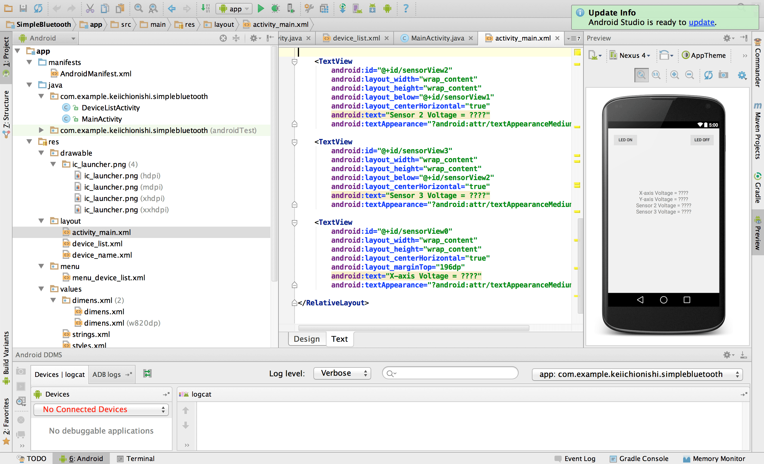
Step 7: Programming Android App: Failed, then triage...sigh
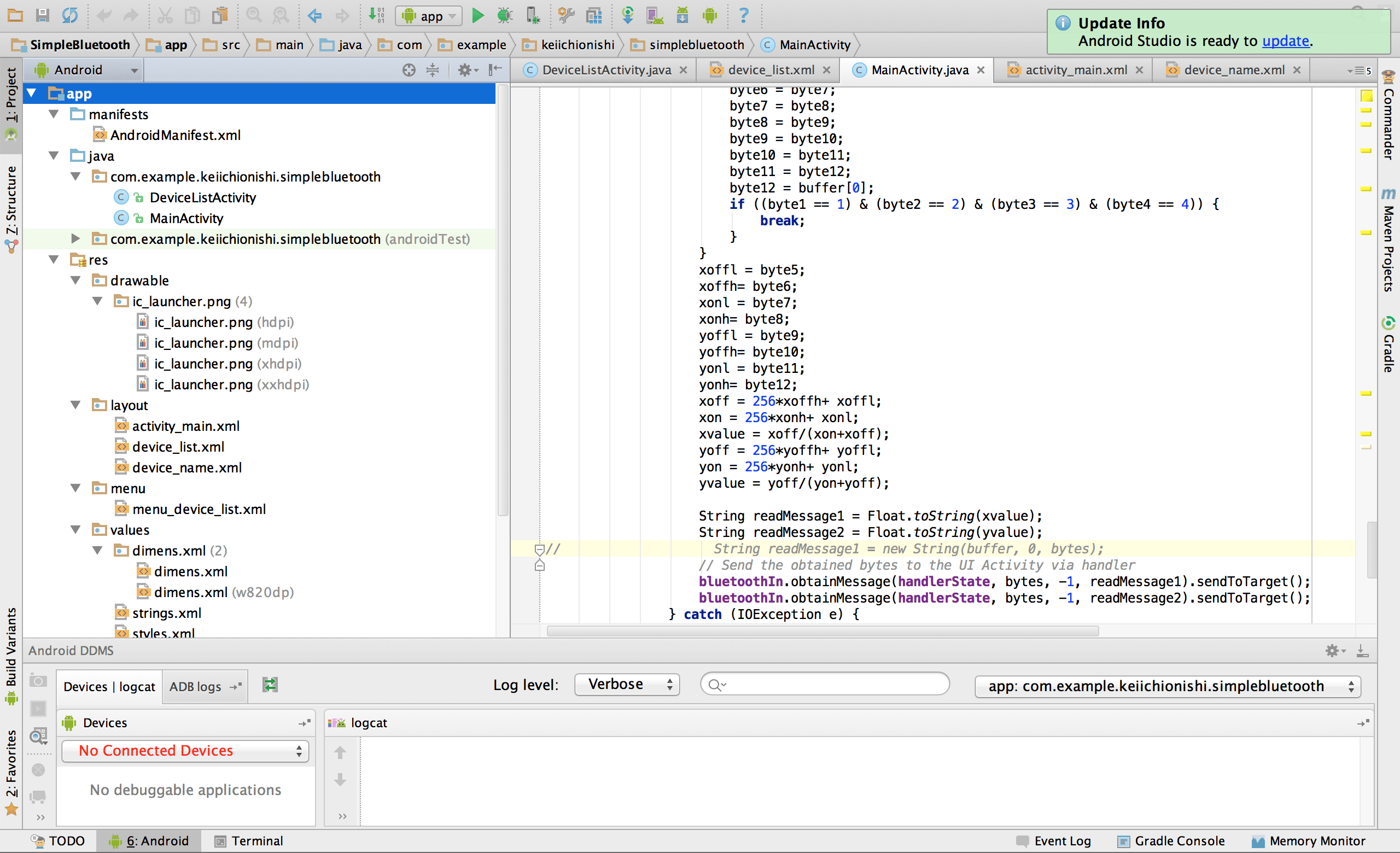
This step is the most challenging part for me. For the week of Network and Application, I created the very best my first mobile App that can turn on/off a LED light on circuit board with bluetooth serial communication. I thought I got familiar with Android App development as a beginner, so I tried to create App that can receive bytes from my circuit board. As I did two weeks ago, I used Android Studio, which is official Android IDE. You can download the package from here. I referred python code for pulse output monitoring that I mentioned above, but had challenges on how to receive bytes and find framing. Due to my lack of knowledge about Serial communication and Java programming, eventually I couldn't debug my code, and I gave up to create it in a given time frame for final presentaiton. I will leave this to my IAP project.
Step 8: Programming GUI on laptop by python
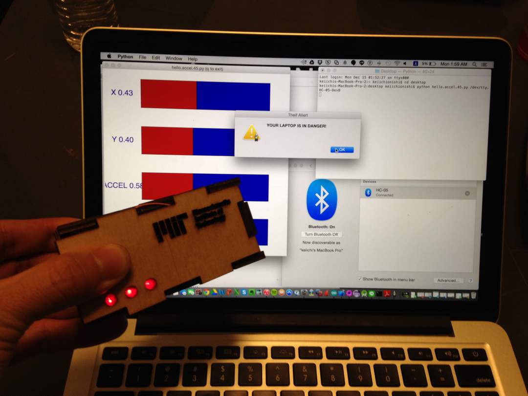
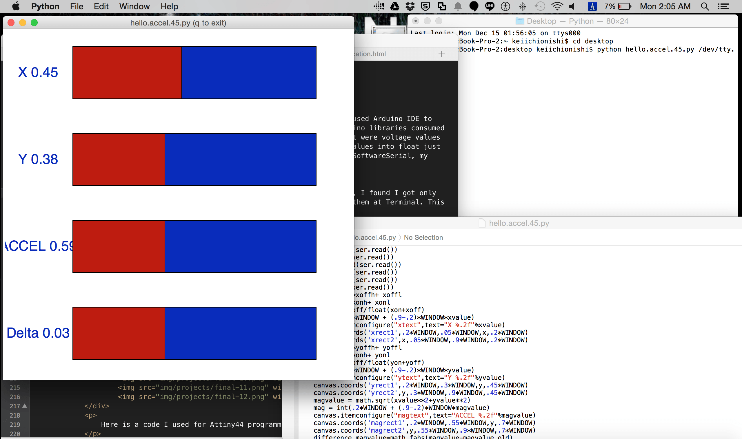
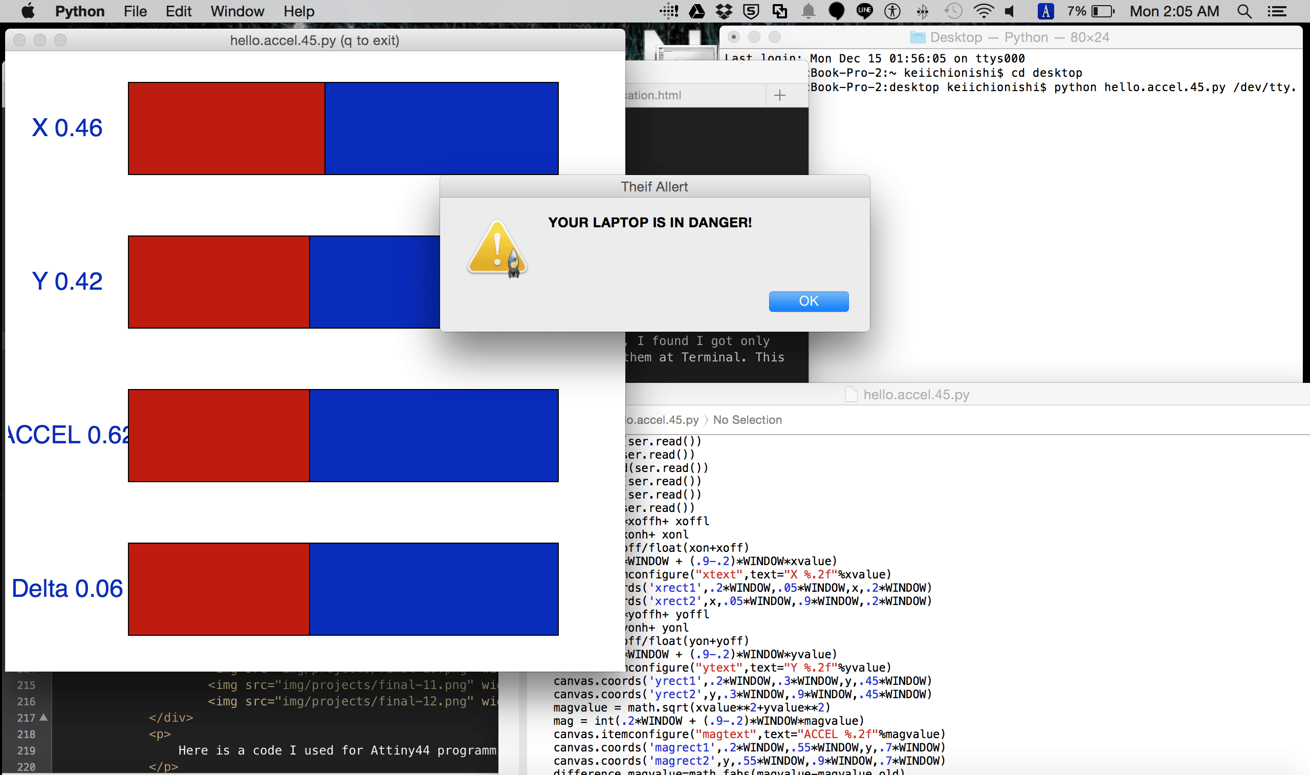
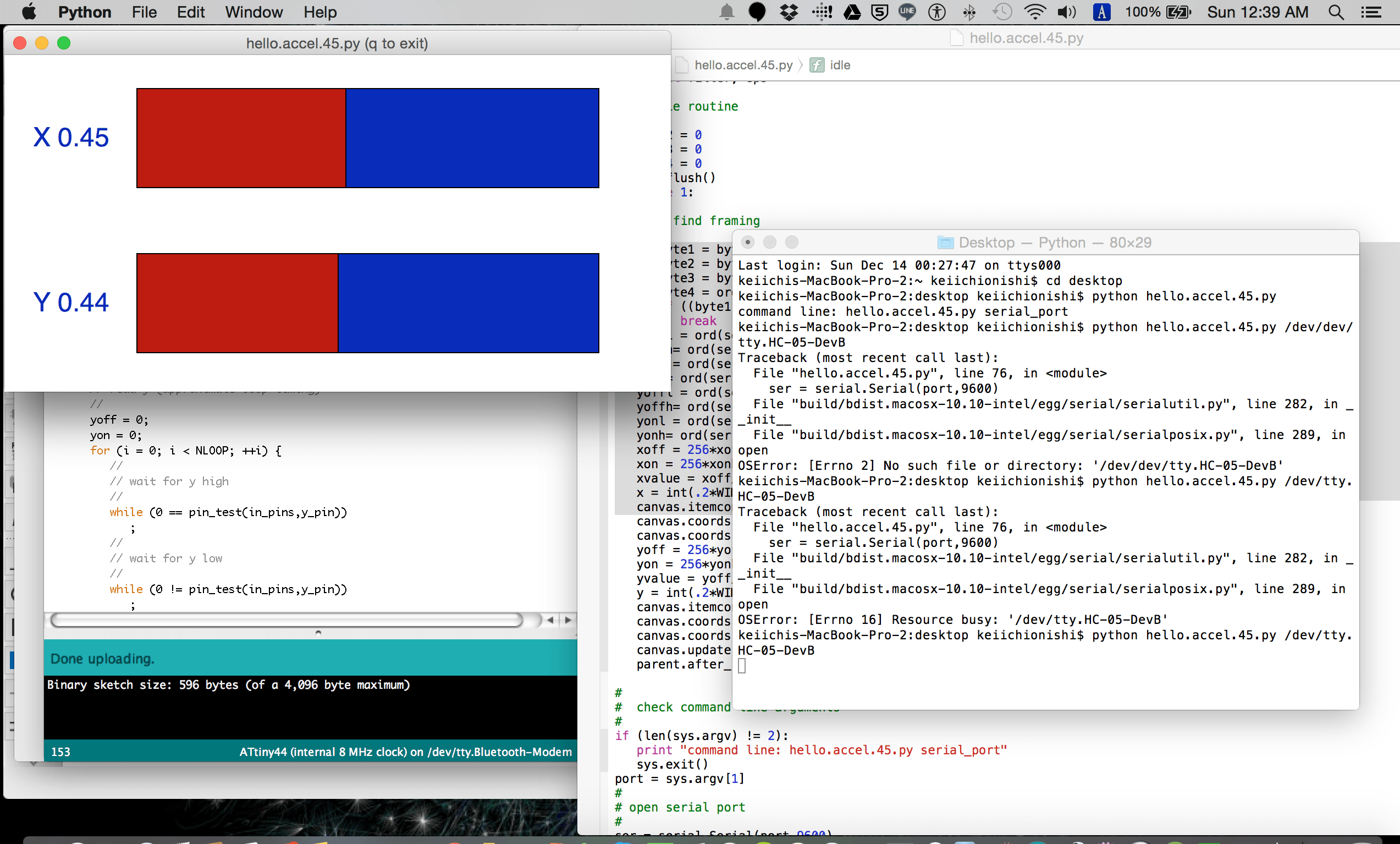
Instead of creating Android App, I decided to code monitoring GUI for laptop trying to realize what I wanted to do on Android phones. Main feature I wanted to realize was giving notification to a user when my device detect abnormal acceleration. What the GUI program needs to do are 1) getting bytes from the circuit board with Bluetooth Serial communication, 2) computing absolute value of acceleration, and 3) giving popup notification to user if the value exceeds threshold. By modifying Neil's sample python code, I achieved #1 quite easily, and computed delta of absolute value of acceleration. #3 was achieved by using tkMessageBox.
Here is GUI code.
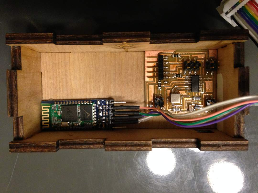
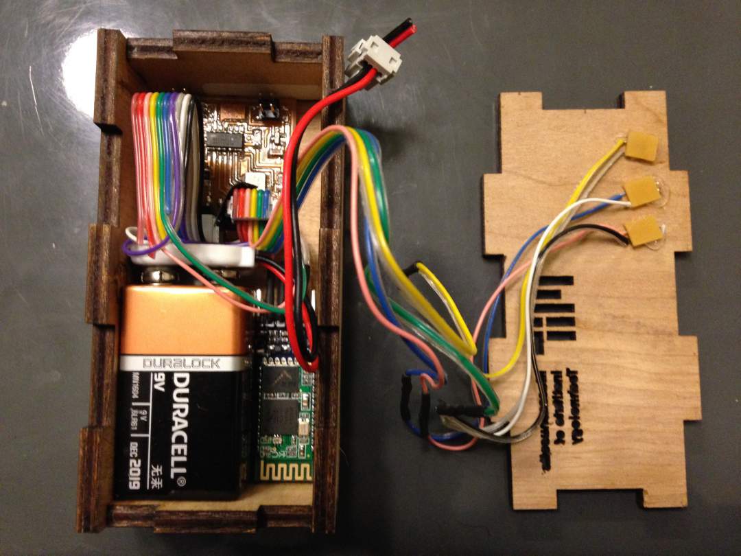
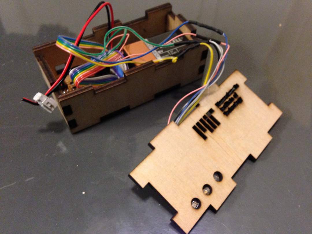
Step 9: Assembly
After I completed all development including hardware, electronics, input and output device, network, and application, I assmebled all into one system. Bringing all componets into one was an exciting experience. One thing I forgot to think about was open/close mechanical structure of the case. I couldn't quite close the case due to no locking mechanism. I need to redesign it for the future.
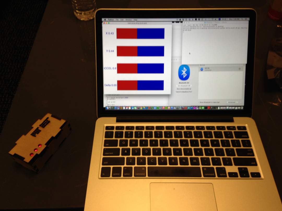
Step 10: Test
I tested the device and it worked properly! I put my device on a laptop and connected to another laptop with bluetooth running python-coded GUI. When I try to remove the laptop, the device senses the movement and successfuly send the information to the laptop and provides notification to me. I would say the system worked well in terms of its function.
What I could do better are 1) adding physical or software switch to turn on/off the device because once I hook up battery to circuit board it would keep consuming electricity, 2) creating Android App sticking to original plan and use case!, 3) making the device smaller, and 4) setting appropriate threshold to detect acceleration of the device eliminating noises. These four items would be definitely my IAP project.