1. Read the instruction sheet carefully to login the computer and connect to the printer to mill the board.
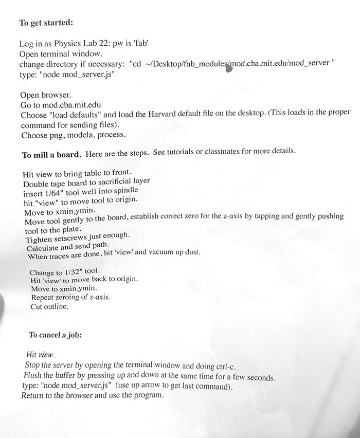
Instruction sheet
2. Prepare the tool for the printer. The quality of the print head is critical. I milled few boards with bad head, and the result is rough and hard to use. I used all the default number and they work well. No need to change depth. After milling the board, we can clean the edges with sand paper to make sure everything clean and flat.
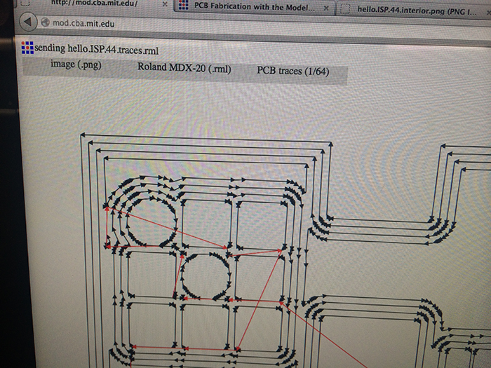
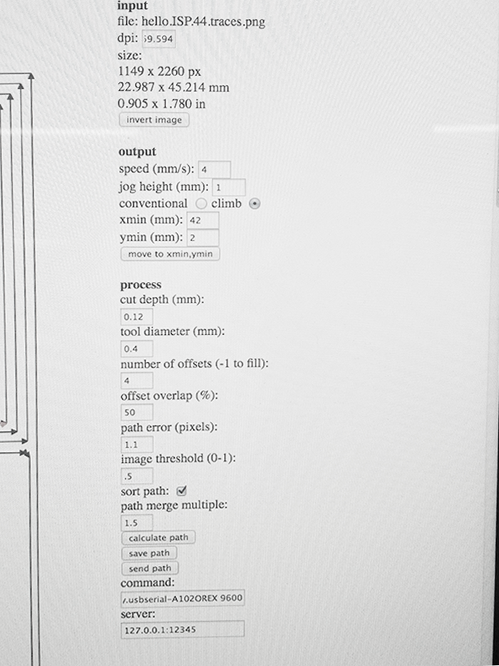
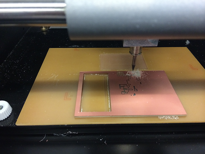
Note: Don't set the xmin number too high. It is easy to exceed the material boundary .
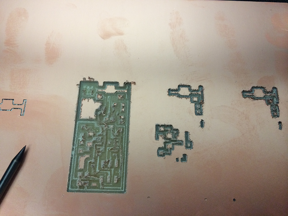
The broken print head causes rough milling edges
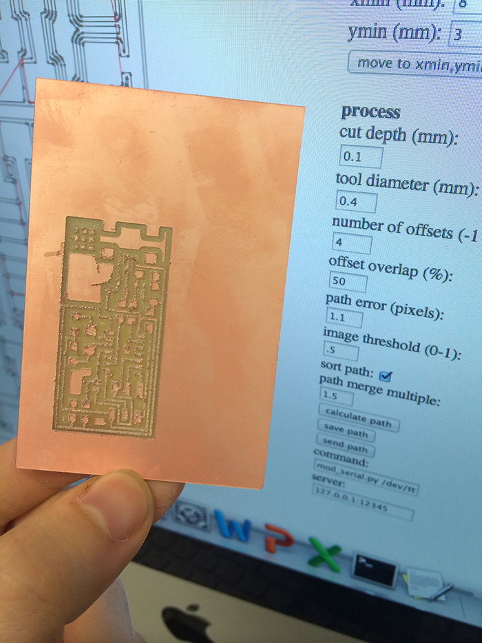
The low quality result
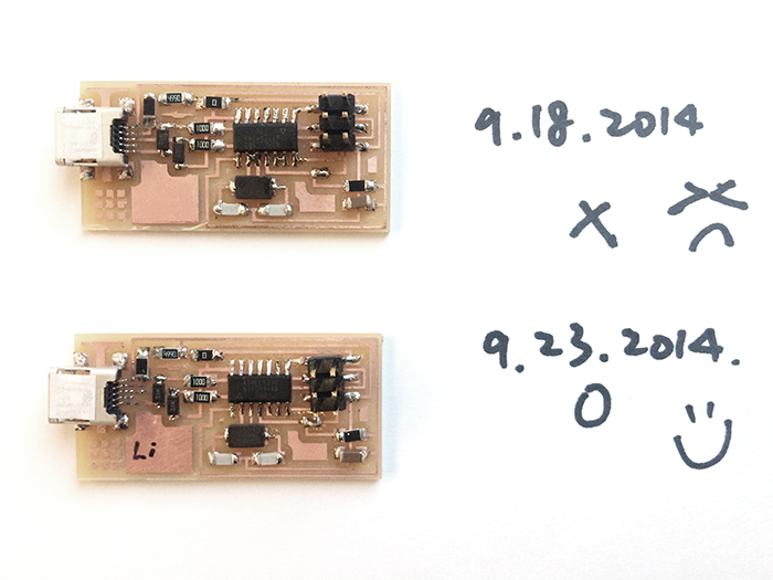
3. Preparing soldering tools set. It took me a while to get familiar with soldering tools. And, the soldering quality does matter. The poor soldering quality makes the poor connection and failed my first board.
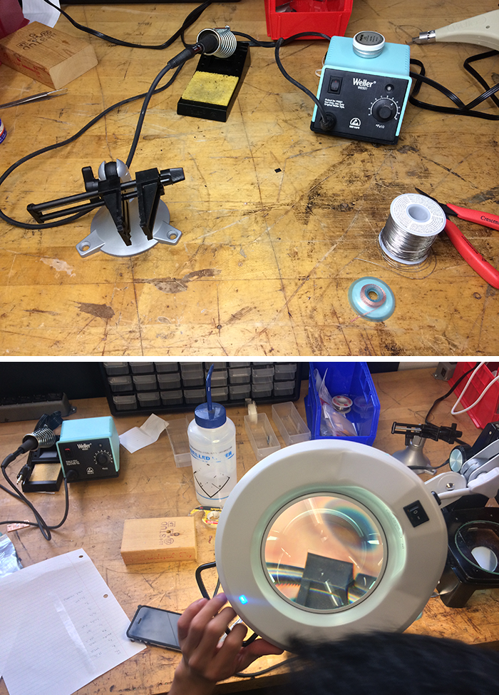
tools set
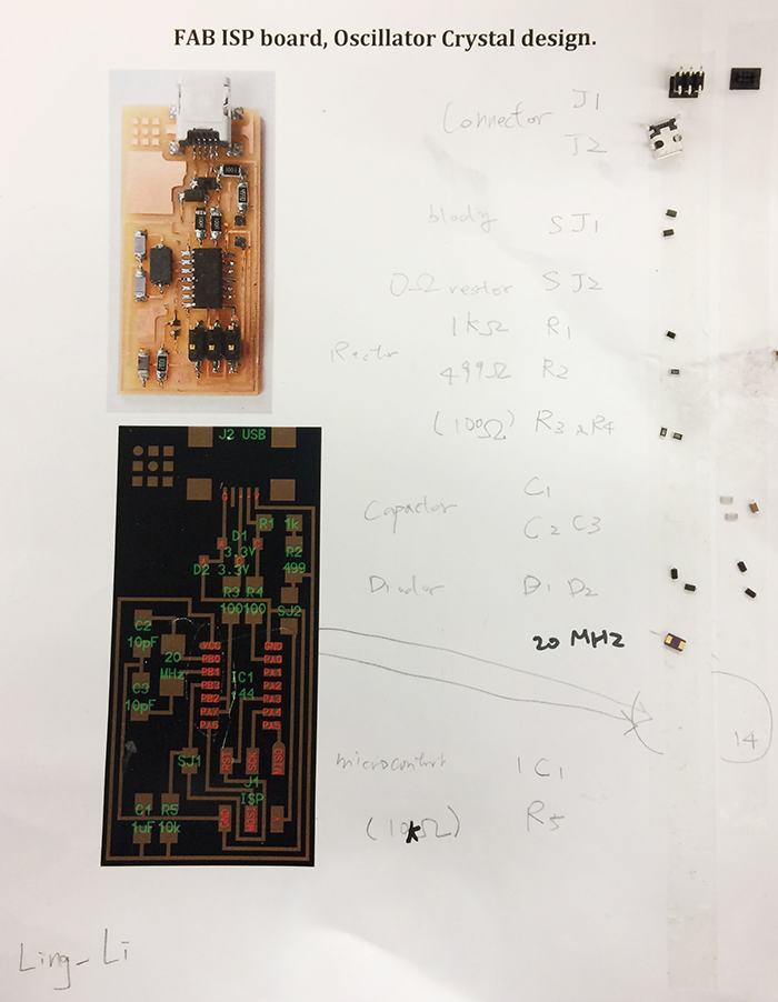
prepare the components
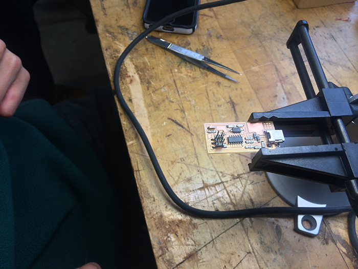
Note: be careful about the direction of microcontroller, I located it wrong at the first time.
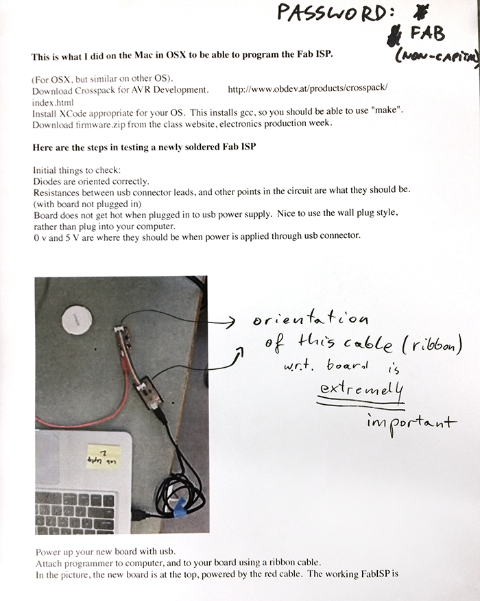
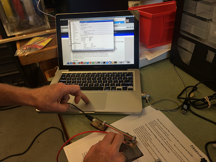
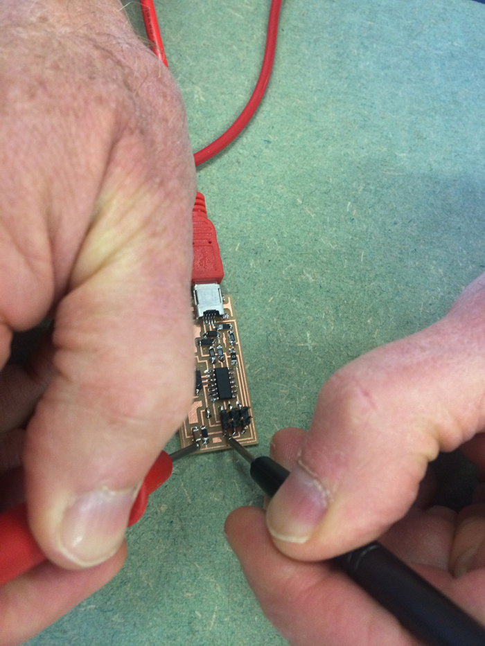
Final Result
