
Final Project Concept: Wooden Speakers
This idea was inspired by two other students' wooden iPad holders, which unfortunately I can't find again to link to here, and my classmate Jasmine's plan to make a clock from Harry Potter with a stylish wooden case.
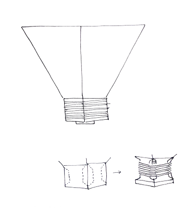
Here's how I imagine the case looking:

(Clearly some elements still need filling in: volume control, audio jack, power cord or battery compartment, handles...)
The decoration could be etched in the case, cut out completely, or cut out most of the way.
To keep a consistent aesthetic, I'd like to see if it's possible to make passable speaker cones out of wood, as imagined above. It's important that speaker cone material be stiff and light enough to pass frequencies in the audible range without buckling (a modest goal might be 500 Hz - 10 kHz, more ambitious would be 30 Hz - 15 kHz). So balsa wood might work. As far as I can tell from a little bit of research, the cones don't necessarily need to be conical (in my drawing above they are pyramids), which means I can avoid bending wood.
It would be cool to make the speaker cone flexures out of wood as well! Here are some initial ideas for ways to make these and the cones. Some of these ideas might be terrible from an audio perspective--it should be relatively easy to test them and find out.

Meanwhile I'm making speaker electronics in another class, so I should be able to reuse some of those designs here.
Final Project Work and Results:
I decided to start with the electronics for this project. Initially I planned to build my own class-D amplifier from scratch, but decided to do something less ambitious first since time was getting short. The best option in the fab inventory was the LM4861M-ND, a 1.5W analog amplifier, but we were out of those so I kept looking around until I found something similar, an LM386N-3, which is also low power (1.25 W).
I used the application note to design a circuit using this amp with a gain of 50 (min 20, max 200). I had to learn how to add parts to an Eagle library for this--can you spot the inelegant ones that are mine?
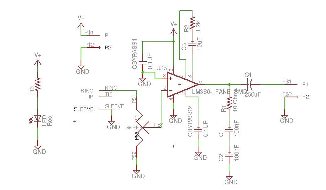
The audio amp IC is through-hole, so initially I tried designing for that, but gave up after several tries failed (first the holes turned out too big, second the solder wouldn't stay in the holes.
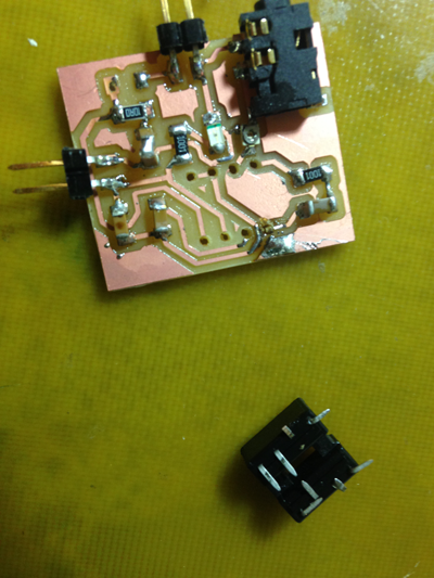
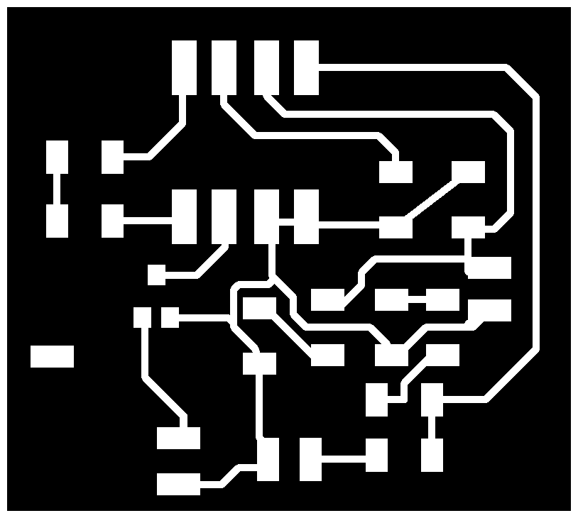
I'm sure I could have asked for tips, but it happened to be late at night with no one else around, and I decided it would be quicker to lay out a new board with a surface-mount package for the amplifier. I just bent the pins out and solder them down onto the pads.
I tested the amp with a power supply and a little 8-Ohm speaker from the inventory, and it worked! I did have to adjust the setpoint of the 10K pot to keep the input voltage from exceeding the amp's rating for music turned at maximum volume.
Next I needed a voice coil. The LM386 is rated for 8 Ohms, so I needed something narrow enough to achieve this in a reasonable number of turns, but wide enough to be able to sustain currents of up to Vout/R = (amp gain) * Vin / R = ~50 * ~0.4/ ~8 = about 0.25 Amps. I had read somewhere that mid-range speakers might use something like 10 meters of 33 gauge wire, which seemed reasonable, but then I found a reference stating that that gauge could only handle about 0.012 A, and wondered how so low a current limit could work in commercial mid-range amps. Here Jeff helpfully explained to me that current ratings for wire vary a lot depending on the application and safety factor, and suggested using twice the "chassis current" rating might be a good metric for my application. According to this reference the maximum current would be far above the 0.25 A I thought I'd need.
It turned out that there weren't that many readily-available choices for thin magnet wire around anyway, so I tried using some 30-gauge wire I had on hand. The resistance per meter was reasonable, and I estimated it would take 240 turns to get to 7 Ohms (for a voice coil with anominal impedance of 8 Ohms, the DC impedance varies, but is somewhere around 6 or 7 according to what I've read. It seemed safer to go too high than too low). 240 turns wasn't enough, so I calculated that I needed 84 more and added 95, at which point the resistance was just above 7.

The coil was wrapped around a roll of paper wide enough to fit over a stack of small magnets I'd found in the inventory. Putting the magnet stack on one paper plate and the voice coil (connected to the amp) on another, with paper flexures in between, I still got some sound (albeit very faint). So the voice coil was working.
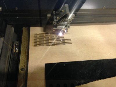
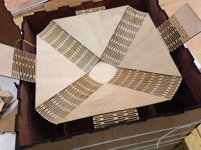
With the electical part of the system demonstrating basic functionality, I switched to Solidworks to design the speaker cone and cabinet (case). For materials, I visited Boulter Plywood in Somerville, where I got 16 square feet of 1/64" mahogany plywood ($30, the cheapest they had there!) for the cone as well as 8 square feet of 1/4" maple plywood ($10) for the case. 1/64" seemed light enough that it might work as speaker cone material. Initially I wanted to cut the cone out of a single piece of plywood, with scoring to achieve the cone shape, but I knew from other students' experience that scoring plywood only works well in the direction of the grain--otherwise it breaks. So instead I decided to glue four scored pieces to four solidpieces as shown below. Getting the settings right and getting consistent cuts from the laser cutter on thin, slightly warped plywood took a lot of tries. But when I got the settings right, the joints were very flexible, bending a full 180 degrees without breaking.

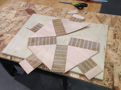
Laying out the cone and glueing all but two pieces together, so it can dry flat:
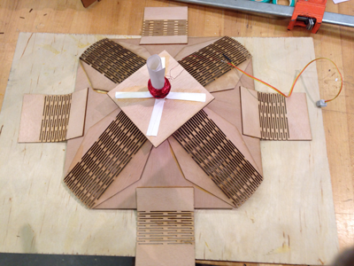
Glueing the final two pieces together to make a 3d shape. Around the edges are the living hinges (more scored 1/64" plywood) that will connect the cone to the case:
I then cut a press-fit box for the case, which I also designed in Solidworks using the Linear Pattern feature, and tested in cardboard before cutting plywood. I glued the bottom and sides together, wrapped string around the whole thing, and let it dry:

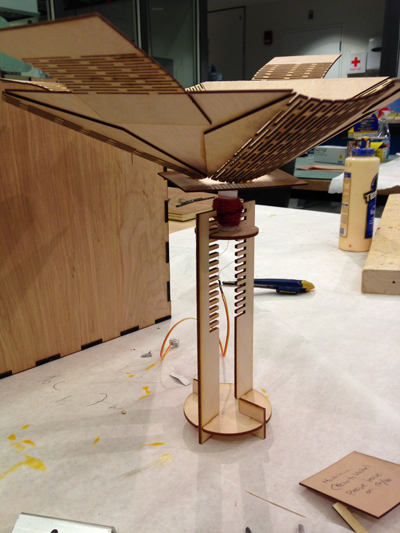
Next I used some 1/8" birch (?) plywood a that friend contributed to laser cut a stand for the magnet stack. Since the magnets would have to be aligned pretty well with the voice coil, and I couldn't know the coil's position precisely, I decided to make a stand that would let me adjust the position of the magnet stack in three dimensions. In this design, we can make course adjustments to the vertical position by moving the upper plate carrying the magnets to different rungs. The plate has some horizontal play, and the magnets themselves can also be moved around on the plate (they're attached by an additional magnet on the bottom.) The top plate is supported such that it can be moved to a different rung even after the stand is glued down to the bottom of the case.

Here's the interior of the box with the magnet stage and the voice coil (amp PCB not shown).

I added pockets to the inside walls of the case, so that the flexures on the cone could be attached to the case in a non-permanent way (otherwise the electronics and everything else would be inaccessible, and there would be no way to adjust the magnet position).

And's the final speaker without the top lid. Not shown is a hole for power and audio cables coming out of the back panel.
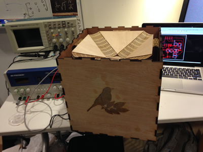
It felt good to hear music come out of the box. The volume maxes out pretty low and there's a fair amount of distortion, but the music is definitely recognizeable.
If I were going to continue improving this, my next step would be to read more about acoustics and speaker cabinet design and figure out how to make this better by changing the shape or size of the cone and case, or adding/removing opening in various places. I a guessing a lot of the sound is coming from the case itself resonating at low frequencies--it's really the size of a subwoofer. Also, the sound improves when I lift the speaker up or put it on spacers.
Deprecated Final Project Idea: A Heliotropic Mirror for More Indoor Sunlight
I love waking up to lots of sunlight. There's plenty of sun outside my windows most mornings, but a lot of it doesn't make it inside.
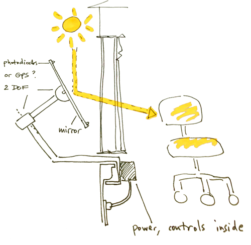
Maybe I can improve the situation by installing a mirror just outside my window to direct some of the light towards my bed.
Actuation:
At a minimum there need to be two degrees of freedom to control the orientation of the mirror. Directing light from a source at one arbitrary location to a destination at some other arbitrary location would require something more complicated, but it might work alright with 2 d.o.f. as a starting point. So I can start with just two servos.
If there's enough friction in the joints that they can passively hold any orientation, then the actuators can move once every hour or so and otherwise be off. That way the power requirement can be low.
Sensing:
The easiest solution might be using a set of photodiodes to measure the direction where the most sunlight is coming from. These could be attached at various places around the mirror.
Another option would be to use GPS, a clock, and almanac data to determine the orientation of the sun relative to the mirror's location on earth. We still need to know the position and orientation of the mirror relative to the sun and the target. That we could calculate by hard-coding in the orientation of the base of the mirror (rigidly attached to the window frame), the geometry of the arm, and the location of the light target (e.g. a bed or desk) relative to the base of the mirror, and by measuring joint angles.