Week 9
Composites.
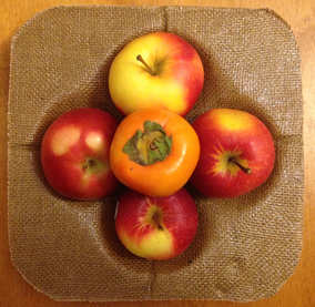
A Fiber Composite Potential Energy Well Fruit Tray

Introduction
This week's assignment was to design and make a 3D mold and produce a fiber composite part. I decided to make a fruit tray - the indentations in the tray represent potential energy wells. I designed my mold in SolidWorks, and I used the Shopbot Buddy Alpha to cut the mold out of foam.
Design
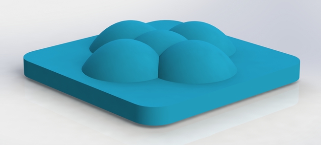
Here's a rendering of the tray mold as designed in SolidWorks. You can think of the geometry as consisting of five overlapping potential energy wells, each the perfect size for holding an apple at stable equilibrium.
Make

Fabricating the Composite Mold
Here are the settings I used to design the toolpaths on PartWorks 3D. I was not too concerned with very fine resolution because the composite does not pickup much detail from the mold. I used a 0.5" upcut endmill for both the roughing and finishing cuts.
Roughing Toolpath Settings:
- Pass Depth: 0.75"
- Stepover: 0.15"
- Spindle Speed: 12000 rpm
- Feed Rate: 5.0"/sec
- Plunge Rate: 2.5"/sec
- Chip Load = (5"/s * 60 s/min) / (12000 rpm * 2 flutes) = 0.0125"
Finishing Toolpath Settings:
- Stepover: 0.10"
- Spindle Speed: 12000 rpm
- Feed Rate: 4.0"/sec
- Plunge Rate: 2.5"/sec
- Chip Load = (4"/s * 60 s/min) / (12000 rpm * 2 flutes) = 0.0100"
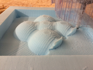
The ShopBot Buddy Alpha working on the finishing cut.
Fabricating the Composites
To make the composite, I used two sheets of burlap as the fibers, embedded in a matrix of Super Sap epoxy bio-resin. To create the fiber composite, I used the vacuum bagging technique. I've drawn a diagram below to illustrate the setup. Make sure to layup the fiber layers with epoxy resin before placing them into the vacuum bag.

A diagram of the setup for vacuum bagging a one-sided mold.
All the above goes into a vacuum bag for the time during which the resin matrix cures.
Explanation of the layers:
1) The burlap heat-sink takes up the heat generated by the exothermic reaction of curing resin.
2) The release film allows the composite to be easily removed from the mold (make sure to spray a release on this layer!).
3) Next, the fiber composites, already permeated with a resin matrix, are placed on top.
4) After this, a bleeder layer (perforated film) allows movement of excess resin to the polyester breather layer, which soaks up the resin.
5) Lastly, seal all the above into a vacuum bag with a one-way valve vacuum connector attached.
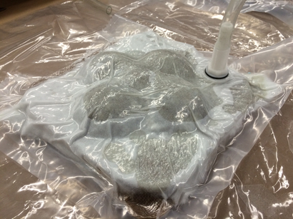
Here's my setup, after placing all the necessary materials inside the vacuum bag.
Unfortunately, I seemed to have a leak in my vacuum bag, and thus, I was forced to leave the pump on. Make sure to seal the edges of the vacuum bag properly. If the edges are heat-sealed with wrinkles, chances are that the air will find a way to equilibrate pressure.
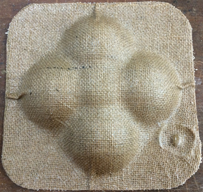
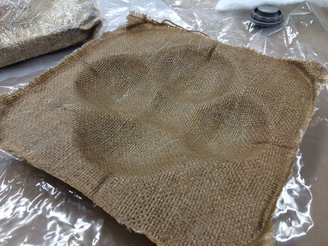
After a couple hours of anxious waiting, I saw the fruits of my labor. I am pretty satisfied with the turnout. I believe I had a good ratio of burlap to epoxy resin - the tray is not brittle; sturdy, but flexible. The composite picked up the geometry of the mold rather pretty well. I trimmed off the edges of my composite with a vertical bandsaw.
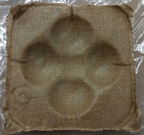
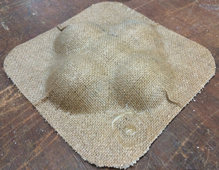
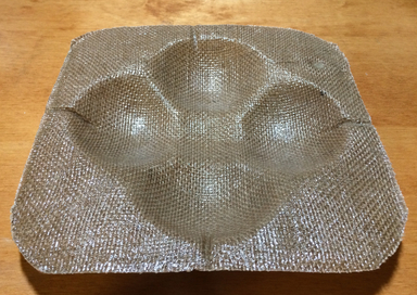
The finished composite part. Note the rings of excess resin formed around the vacuum connector.
An interesting note is that one crease formed at each of the four bordering potential energy wells in a very regular pattern, which I did not expect. In addition, the vacuum connector caused a formation of resin rings at its location. Fortunately, this formed at the bottom of the fruit tray, where it is less noticeable. I did make sure that the vacuum connector was not directly on top of the mold, but is there a better location for placement?
Lessons Learned
1) Seal the vacuum bag properly. Check that all the edges are heat-sealed and ensure that the connector used to connect the vacuum to the bag is air-tight.
2) Design the mold for less post-processing work. I ended-up using a bandsaw to remove excess edges on my foam mold. It will save you time, however, to simply make this a part of your CAD model, and let the CNC automatically do this for you.
3) Account for the position of the vacuum connector in your mold/composite design. The vacuum connector tends to pull resin towards it, creating noticeable rings of cured resin.